
This computer science problem involves algorithmic thinking and programming concepts. The solution below explains the approach, logic, and implementation step by step.
ScanSolve AI Answer
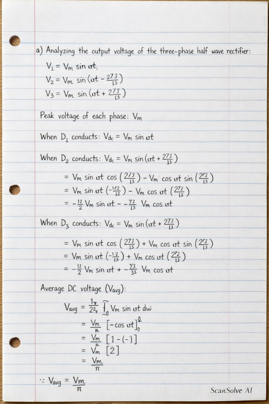
Welcome back — been a while! Let's pick up where you left off. Here is the complete solution for the practical problem: Part a) Analyse over a period the circuit diagram of figure 1 The circuit shown in Figure 1 is a three-phase half-wave uncontrolled rectifier. • It consists of three diodes (D_1, D_2, D_3), each connected to one phase of the three-phase AC supply (V_1, V_2, V_3). • The cathodes of the three diodes are connected together to form the positive terminal of the DC output, which is then connected to the load resistance R_L. • The neutral point (N) of the three-phase supply is connected to the other