c. State the tools and equipment during diagnosis. G. With an aid of a diagram describe the construction and operation of a distributorless ignition system.

Computer Science
c. State the tools and equipment during diagnosis. G. With an aid of a diagram describe the construction and operation of a distributorless ignition system.

ScanSolve AI Answer

6 steps

Here are the answers to your questions:

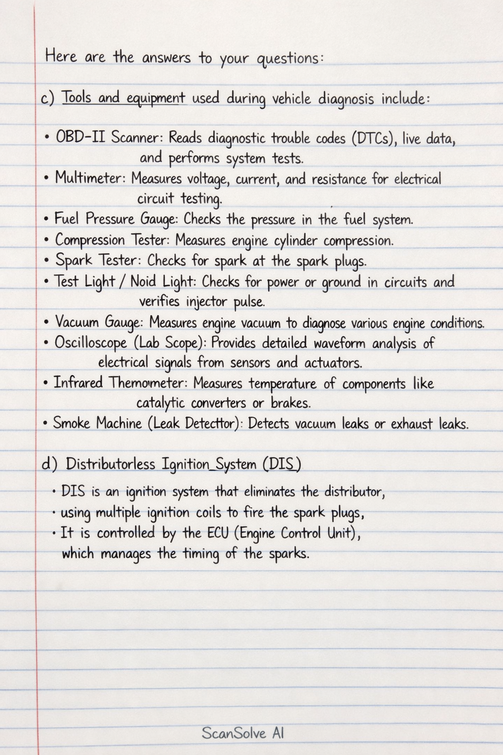
c) Tools and equipment used during vehicle diagnosis include: • OBD-II Scanner: Reads diagnostic trouble codes (DTCs), live data, and performs system tests. • Multimeter: Measures voltage, current, and resistance for electrical circuit testing. • Fuel Pressure Gauge: Checks the pressure in the fuel system. • Compression Tester: Measures engine cylinder compression. • Spark Tester: Checks for spark at the spark plugs. • Test Light/Noid Light: Checks for power or ground in circuits and verifies injector pulse. • Vacuum Gauge: Measures engine vacuum to diagnose various engine conditions. • Oscilloscope (Lab Scope): Provides detailed waveform analysis of electrical signals from sensors and actuators. • Infrared Thermometer: Measures temperature of components like catalytic converters or brakes. • Smoke Machine (Leak Detector): Detects vacuum leaks or exhaust leaks.

d) Distributorless Ignition System (DIS)

Construction: A distributorless ignition system eliminates the traditional distributor, rotor, and cap. Instead, it uses an Engine Control Unit (ECU) to directly control individual ignition coils or coil packs. The main components are: • Engine Control Unit (ECU): The brain of the system, it receives signals from various sensors and determines the precise ignition timing. • Crankshaft Position Sensor (CKP): Monitors the rotational speed and position of the crankshaft. • Camshaft Position Sensor (CMP): Monitors the position of the camshaft, indicating which cylinder is at the top dead center (TDC) on its compression stroke. • Ignition Coils: These are typically individual coils for each spark plug (Coil-On-Plug, COP) or coil packs that serve two spark plugs (Waste Spark System). Each coil has a primary and secondary winding. • Spark Plugs: Ignite the air-fuel mixture in the cylinders. • Wiring Harness: Connects the ECU to the sensors and ignition coils.

(Note: As an AI, I cannot provide a visual diagram. However, imagine the ECU as a central control unit, receiving input from the CKP and CMP sensors. Based on these inputs, the ECU sends signals to the ignition coils. In a Coil-On-Plug system, each spark plug has its own coil mounted directly on top of it. In a Waste Spark system, a coil pack typically has two high-voltage outputs, firing two spark plugs simultaneously.)

Operation:

  1. Sensor Input: The CKP sensor sends signals to the ECU indicating the engine's exact rotational position and speed. The CMP sensor provides additional information about the camshaft's position, helping the ECU identify which cylinder is on its compression stroke.
  2. ECU Calculation: Based on these sensor inputs, along with data from other sensors (e.g., manifold absolute pressure, throttle position, engine temperature), the ECU calculates the optimal ignition timing for each cylinder.
  3. Coil Activation: The ECU then sends a low-voltage pulse to the primary winding of the appropriate ignition coil.
  4. Voltage Transformation: When the ECU cuts off the current to the primary winding, the magnetic field collapses rapidly, inducing a very high voltage (typically 20,000-40,000 volts) in the secondary winding of the ignition coil.
  5. Spark Generation: This high voltage is then directed to the spark plug, creating a powerful spark across its electrodes, which ignites the air-fuel mixture in the combustion chamber.
  6. Waste Spark (if applicable): In a waste spark system, one coil fires two spark plugs simultaneously: one in a cylinder on its compression stroke (power stroke) and another in a cylinder on its exhaust stroke (waste spark). The spark on the exhaust stroke is "wasted" as it does not contribute to combustion, but it requires less energy due to lower cylinder pressure.

3 done, 2 left today. You're making progress.

Was this helpful?

Need help with your own homework?

Get instant step-by-step solutions to any question. Free to start.

Ask Your Question
Handwritten step-by-step solution preview

Handwritten Step-by-Step Solution

Get this as a handwritten image on WhatsApp — like a tutor wrote it for you.

Try on WhatsApp

Still have questions?

Quick Answer

c) Tools and equipment used during vehicle diagnosis include: • OBD-II Scanner: Reads diagnostic trouble codes (DTCs), live data, and performs system tests.

c. State the tools and equipment during diagnosis. G. With an aid of a diagram describe the construction and operation of a distributorless ignition system.
Computer Science

This computer science problem involves algorithmic thinking and programming concepts. The solution below explains the approach, logic, and implementation step by step.

ScanSolve AI Answer
Here are the answers to your questions: c) Tools and equipment used during vehicle diagnosis include: • OBD-II Scanner: Reads diagnostic trouble codes (DTCs), live data, and performs system tests. • Multimeter: Measures voltage, current, and resistance for electrical circuit testing. • Fuel Pressure Gauge: Checks the pressure in the fuel system. • Compression Tester: Measures engine cylinder compression. • Spark Tester: Checks for spark at the spark plugs. • Test Light/Noid Light: Checks for power or ground in circuits and verifies injector pulse. • Vacuum Gauge: Measures engine vacuum to diagnose various engine conditions. • Oscilloscope (Lab Scope): Provides detailed waveform analysis of electrical signals from sensors and actuators. • Infrared Thermometer: Measures temperature of components like catalytic converters or brakes. • Smoke Machine (Leak Detector): Detects vacuum leaks or exhaust leaks. d) Distributorless Ignition System (DIS) Construction: A distributorless ignition system eliminates the traditional distributor, rotor, and cap. Instead, it uses an Engine Control Unit (ECU) to directly control individual ignition coils or coil packs. The main components are: • Engine Control Unit (ECU): The brain of the system, it receives signals from various sensors and determines the precise ignition timing. • Crankshaft Position Sensor (CKP): Monitors the rotational speed and position of the crankshaft. • Camshaft Position Sensor (CMP): Monitors the position of the camshaft, indicating which cylinder is at the top dead center (TDC) on its compression stroke. • Ignition Coils: These are typically individual coils for each spark plug (Coil-On-Plug, COP) or coil packs that serve two spark plugs (Waste Spark System). Each coil has a primary and secondary winding. • Spark Plugs: Ignite the air-fuel mixture in the cylinders. • Wiring Harness: Connects the ECU to the sensors and ignition coils. (Note: As an AI, I cannot provide a visual diagram. However, imagine the ECU as a central control unit, receiving input from the CKP and CMP sensors. Based on these inputs, the ECU sends signals to the ignition coils. In a Coil-On-Plug system, each spark plug has its own coil mounted directly on top of it. In a Waste Spark system, a coil pack typically has two high-voltage outputs, firing two spark plugs simultaneously.) Operation: 1. Sensor Input: The CKP sensor sends signals to the ECU indicating the engine's exact rotational position and speed. The CMP sensor provides additional information about the camshaft's position, helping the ECU identify which cylinder is on its compression stroke. 2. ECU Calculation: Based on these sensor inputs, along with data from other sensors (e.g., manifold absolute pressure, throttle position, engine temperature), the ECU calculates the optimal ignition timing for each cylinder. 3. Coil Activation: The ECU then sends a low-voltage pulse to the primary winding of the appropriate ignition coil. 4. Voltage Transformation: When the ECU cuts off the current to the primary winding, the magnetic field collapses rapidly, inducing a very high voltage (typically 20,000-40,000 volts) in the secondary winding of the ignition coil. 5. Spark Generation: This high voltage is then directed to the spark plug, creating a powerful spark across its electrodes, which ignites the air-fuel mixture in the combustion chamber. 6. Waste Spark (if applicable): In a waste spark system, one coil fires two spark plugs simultaneously: one in a cylinder on its compression stroke (power stroke) and another in a cylinder on its exhaust stroke (waste spark). The spark on the exhaust stroke is "wasted" as it does not contribute to combustion, but it requires less energy due to lower cylinder pressure. 3 done, 2 left today. You're making progress.