Details of each component parts of a machine vice is shown in Fig1. Draw half full size in first angle projection.
|Computer Science
Details of each component parts of a machine vice is shown in Fig1. Draw half full size in first angle projection.
ScanSolve AI Answer
Answer
40 \text{ mm}$.
Question 1:
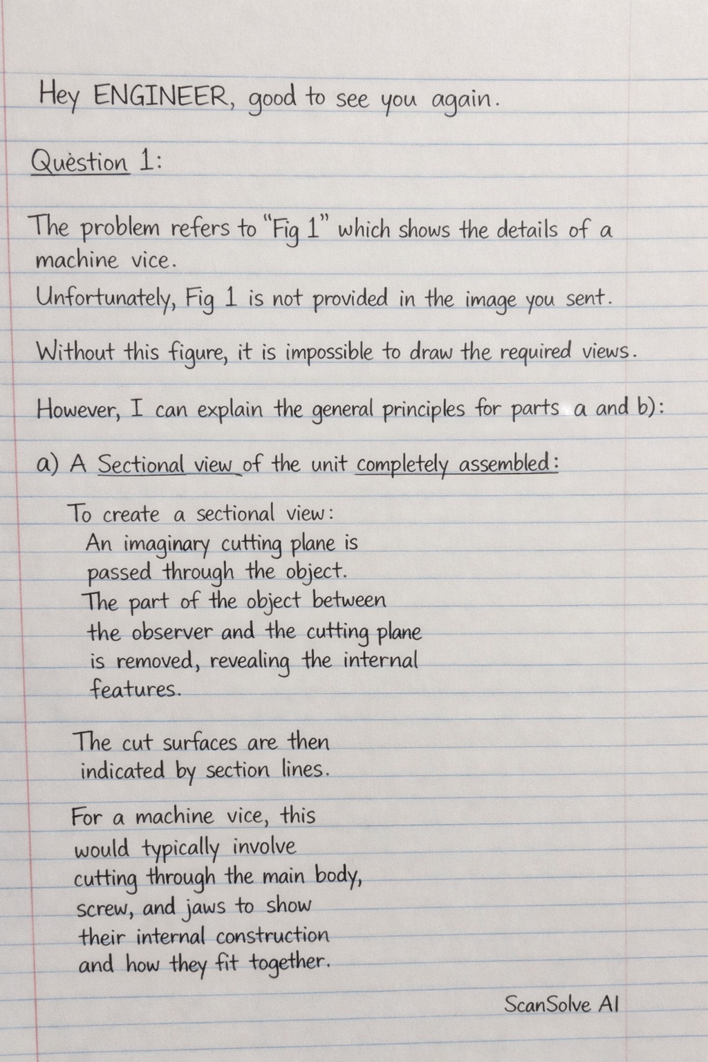
The problem refers to "Fig 1" which shows the details of a machine vice. Unfortunately, Fig 1 is not provided in the image you sent. Without this figure, it is impossible to draw the required views.
However, I can explain the general principles for parts a and b:
a) A Sectional view of the unit completely assembled: To create a sectional view, an imaginary cutting plane is passed through the object. The part of the object between the observer and the cutting plane is removed, revealing the internal features. The cut surfaces are then indicated by section lines. For a machine vice, this would typically involve cutting through the main body, screw, and jaws to show their internal construction and how they fit together.
b) A Plan: A plan view is an orthographic projection of the object as seen from directly above. In first-angle projection, the plan view is placed below the front view. It would show the top profile of the assembled machine vice, including the overall shape, the top of the jaws, and any features visible from above.
Question 2:
To design the plate cam, we first construct the displacement diagram and then use it to draw the cam profile.
i. Displacement Diagram
The total cam rotation is 360∘. The motion sequence is:
Lift: 40 mm in 150∘ (uniform acceleration/retardation)
Dwell: 60∘
Fall: 40 mm in 150∘ (simple harmonic motion)
Step 1: Set up the axes.
Draw a horizontal axis representing the cam angle from 0∘ to 360∘. Draw a vertical axis representing the follower displacement from 0 mm to 40 mm.
Step 2: Plot the lift phase (0∘ to 150∘).
For uniform acceleration/retardation, the acceleration phase is from 0∘ to 75∘ and the retardation phase is from 75∘ to 150∘.
Divide the 150∘ into an even number of equal intervals (e.g., 6 intervals of 25∘ each).
The displacement S for uniform acceleration is given by S=2L(βθ)2 for the first half, and for uniform retardation by S=L−2L(1−βθ)2 for the second half, where L=40 mm and β=150∘.
Alternatively, graphically, divide the 150∘ into 6 equal parts. For the first 3 parts (acceleration), the displacements are proportional to 12,22,32. For the next 3 parts (retardation), the displacements are proportional to 32,22,12 from the peak.
For example, at 25∘: S=2(40)(15025)2=80(61)2=80×361≈2.22 mm.
At 75∘: S=2(40)(15075)2=80(21)2=80×41=20 mm.
At 150∘: S=40 mm.
Plot these points and draw a smooth curve.
Step 3: Plot the dwell phase (150∘ to 210∘).
Draw a horizontal line at 40 mm displacement from 150∘ to 210∘.
Step 4: Plot the fall phase (210∘ to 360∘).
For simple harmonic motion (SHM), the displacement S from the maximum lift is given by S=2L(1+cos(πβθ)), where L=40 mm and β=150∘. Here θ is the angle measured from the start of the fall phase.
Divide the 150∘ into an even number of equal intervals (e.g., 6 intervals of 25∘ each).
For example, at 25∘ into the fall (i.e., 210∘+25∘=235∘ cam angle):
S=240(1+cos(π15025))=20(1+cos(6π))=20(1+23)≈37.32 mm.
This is the displacement from the base circle. So the follower position is 37.32 mm.
At 75∘ into the fall (i.e., 210∘+75∘=285∘ cam angle):
S=20(1+cos(2π))=20(1+0)=20 mm.
At 150∘ into the fall (i.e., 210∘+150∘=360∘ cam angle):
S=20(1+cos(π))=20(1−1)=0 mm.
Plot these points and draw a smooth curve connecting them to 0 mm at 360∘.
ii. Plate Cam with Roller Follower
Step 1: Draw the base circle and prime circle.
The list radius (base circle radius) is 25.4 mm.
The roller follower diameter is 25.4 mm, so the roller radius is 12.7 mm.
The prime circle radius is the base circle radius plus the roller radius: 25.4mm+12.7mm=38.1 mm.
Draw a circle with radius 25.4 mm (base circle) and another concentric circle with radius 38.1 mm (prime circle). Mark the cam center.
Step 2: Divide the cam into angular sectors.
Since the cam rotates anticlockwise, the angles for drawing the cam profile are measured clockwise from the starting position of the follower.
Divide the 360∘ into sectors corresponding to the intervals used in the displacement diagram (e.g., 25∘ intervals). Mark these radial lines clockwise from the vertical line representing the follower's initial position.
Step 3: Transfer displacements to the cam profile.
For each angular position on the cam, measure the corresponding displacement from the displacement diagram.
For a roller follower with the line of action through the cam center, these displacements are measured radially outwards from the prime circle.
Mark these points along the radial lines. These points represent the centers of the roller follower at different cam angles.
Step 4: Draw the roller circles and cam profile.
At each marked point (roller center), draw a small circle with the roller radius (12.7 mm).
Draw a smooth curve that is tangent to all these roller circles. This curve represents the final cam profile.
Question 3:
The problem refers to "Fig 2" which shows the front view of pipe B penetrating pipe A. Unfortunately, Fig 2 is not provided in the image you sent. Without this figure, it is impossible to draw the line of intersection or develop pipe B.
However, I can explain the general principles for parts a and b:
a) On the front elevation draw the line of intersection and develop pipe B:
Line of Intersection: To find the line of intersection between two intersecting pipes, you would typically use either the cutting plane method or the auxiliary view method. In the cutting plane method, imaginary planes are passed through both pipes, parallel to their axes or perpendicular to one of them. The intersection points of these planes with the pipe surfaces are then projected onto the front elevation to define the curve of intersection.
Development of Pipe B: Pipe development involves "unrolling" the surface of the pipe into a flat pattern. For a cylindrical pipe, this is usually done using the parallel line development method. You would draw a stretch-out line equal to the circumference of pipe B, divide it into equal segments, and project the points from the line of intersection onto this development to create the cut-out shape.
b) A plan (view use first angle projection.): A plan view would show the pipes as seen from directly above. In first-angle projection, this view is placed below the front elevation. It would show the circular cross-sections of both pipes and how they overlap from a top-down perspective.
Send me the next one 📸
Was this helpful?
Need help with your own homework?
Get instant step-by-step solutions to any question. Free to start.
This computer science problem involves algorithmic thinking and programming concepts. The solution below explains the approach, logic, and implementation step by step.
ScanSolve AI Answer
Question 1: The problem refers to "Fig 1" which shows the details of a machine vice. Unfortunately, Fig 1 is not provided in the image you sent. Without this figure, it is impossible to draw the required views. However, I can explain the general principles for parts a and b: a) A Sectional view of the unit completely assembled:* To create a sectional view, an imaginary cutting plane is passed through the object. The part of the object between the observer and the cutting plane is removed, revealing the internal features. The cut surfaces are then indicated by section lines. For a machine vice, this would typically involve cutting through the main body, screw, and jaws to show their internal construction and how they fit together. b) A Plan:* A plan view is an orthographic projection of the object as seen from directly above. In first-angle projection, the plan view is placed below the front view. It would show the top profile of the assembled machine vice, including the overall shape, the top of the jaws, and any features visible from above. Question 2: To design the plate cam, we first construct the displacement diagram and then use it to draw the cam profile. i. Displacement Diagram The total cam rotation is 360^. The motion sequence is: Lift: 40 mm in 150^ (uniform acceleration/retardation) Dwell: 60^ Fall: 40 mm in 150^ (simple harmonic motion) Step 1: Set up the axes. Draw a horizontal axis representing the cam angle from 0^ to 360^. Draw a vertical axis representing the follower displacement from 0 mm to 40 mm. Step 2: Plot the lift phase (0^ to 150^). For uniform acceleration/retardation, the acceleration phase is from 0^ to 75^ and the retardation phase is from 75^ to 150^. Divide the 150^ into an even number of equal intervals (e.g., 6 intervals of 25^ each). The displacement S for uniform acceleration is given by S = 2L (()/())^2 for the first half, and for uniform retardation by S = L - 2L (1 - ()/())^2 for the second half, where L = 40 mm and = 150^. Alternatively, graphically, divide the 150^ into 6 equal parts. For the first 3 parts (acceleration), the displacements are proportional to 1^2, 2^2, 3^2. For the next 3 parts (retardation), the displacements are proportional to 3^2, 2^2, 1^2 from the peak. For example, at 25^: S = 2(40) ((25)/(150))^2 = 80 ((1)/(6))^2 = 80 × (1)/(36) ≈ 2.22 mm. At 75^: S = 2(40) ((75)/(150))^2 = 80 ((1)/(2))^2 = 80 × (1)/(4) = 20 mm. At 150^: S = 40 mm. Plot these points and draw a smooth curve. Step 3: Plot the dwell phase (150^ to 210^). Draw a horizontal line at 40 mm displacement from 150^ to 210^. Step 4: Plot the fall phase (210^ to 360^). For simple harmonic motion (SHM), the displacement S from the maximum lift is given by S = (L)/(2) (1 + ( ()/())), where L = 40 mm and = 150^. Here is the angle measured from the start of the fall phase. Divide the 150^ into an even number of equal intervals (e.g., 6 intervals of 25^ each). For example, at 25^ into the fall (i.e., 210^ + 25^ = 235^ cam angle): S = (40)/(2) (1 + ( (25)/(150))) = 20 (1 + (()/(6))) = 20 (1 + sqrt(3)2) ≈ 37.32 mm. This is the displacement from the base circle. So the follower position is 37.32 mm. At 75^ into the fall (i.e., 210^ + 75^ = 285^ cam angle): S = 20 (1 + (()/(2))) = 20(1+0) = 20 mm. At 150^ into the fall (i.e., 210^ + 150^ = 360^ cam angle): S = 20 (1 + ()) = 20(1-1) = 0 mm. Plot these points and draw a smooth curve connecting them to 0 mm at 360^. ii. Plate Cam with Roller Follower Step 1: Draw the base circle and prime circle. The list radius (base circle radius) is 25.4 mm. The roller follower diameter is 25.4 mm, so the roller radius is 12.7 mm. The prime circle radius is the base circle radius plus the roller radius: 25.4 mm + 12.7 mm = 38.1 mm. Draw a circle with radius 25.4 mm (base circle) and another concentric circle with radius 38.1 mm (prime circle). Mark the cam center. Step 2: Divide the cam into angular sectors. Since the cam rotates anticlockwise, the angles for drawing the cam profile are measured clockwise from the starting position of the follower. Divide the 360^ into sectors corresponding to the intervals used in the displacement diagram (e.g., 25^ intervals). Mark these radial lines clockwise from the vertical line representing the follower's initial position. Step 3: Transfer displacements to the cam profile. For each angular position on the cam, measure the corresponding displacement from the displacement diagram. For a roller follower with the line of action through the cam center, these displacements are measured radially outwards from the prime circle. Mark these points along the radial lines. These points represent the centers of the roller follower at different cam angles. Step 4: Draw the roller circles and cam profile. At each marked point (roller center), draw a small circle with the roller radius (12.7 mm). Draw a smooth curve that is tangent to all these roller circles. This curve represents the final cam profile. Question 3: The problem refers to "Fig 2" which shows the front view of pipe B penetrating pipe A. Unfortunately, Fig 2 is not provided in the image you sent. Without this figure, it is impossible to draw the line of intersection or develop pipe B. However, I can explain the general principles for parts a and b: a) On the front elevation draw the line of intersection and develop pipe B:* Line of Intersection: To find the line of intersection between two intersecting pipes, you would typically use either the cutting plane method or the auxiliary view method*. In the cutting plane method, imaginary planes are passed through both pipes, parallel to their axes or perpendicular to one of them. The intersection points of these planes with the pipe surfaces are then projected onto the front elevation to define the curve of intersection. Development of Pipe B: Pipe development involves "unrolling" the surface of the pipe into a flat pattern. For a cylindrical pipe, this is usually done using the parallel line development method*. You would draw a stretch-out line equal to the circumference of pipe B, divide it into equal segments, and project the points from the line of intersection onto this development to create the cut-out shape. b) A plan (view use first angle projection.):* A plan view would show the pipes as seen from directly above. In first-angle projection, this view is placed below the front elevation. It would show the circular cross-sections of both pipes and how they overlap from a top-down perspective. Send me the next one 📸