

This computer science problem involves algorithmic thinking and programming concepts. The solution below explains the approach, logic, and implementation step by step.
ScanSolve AI Answer
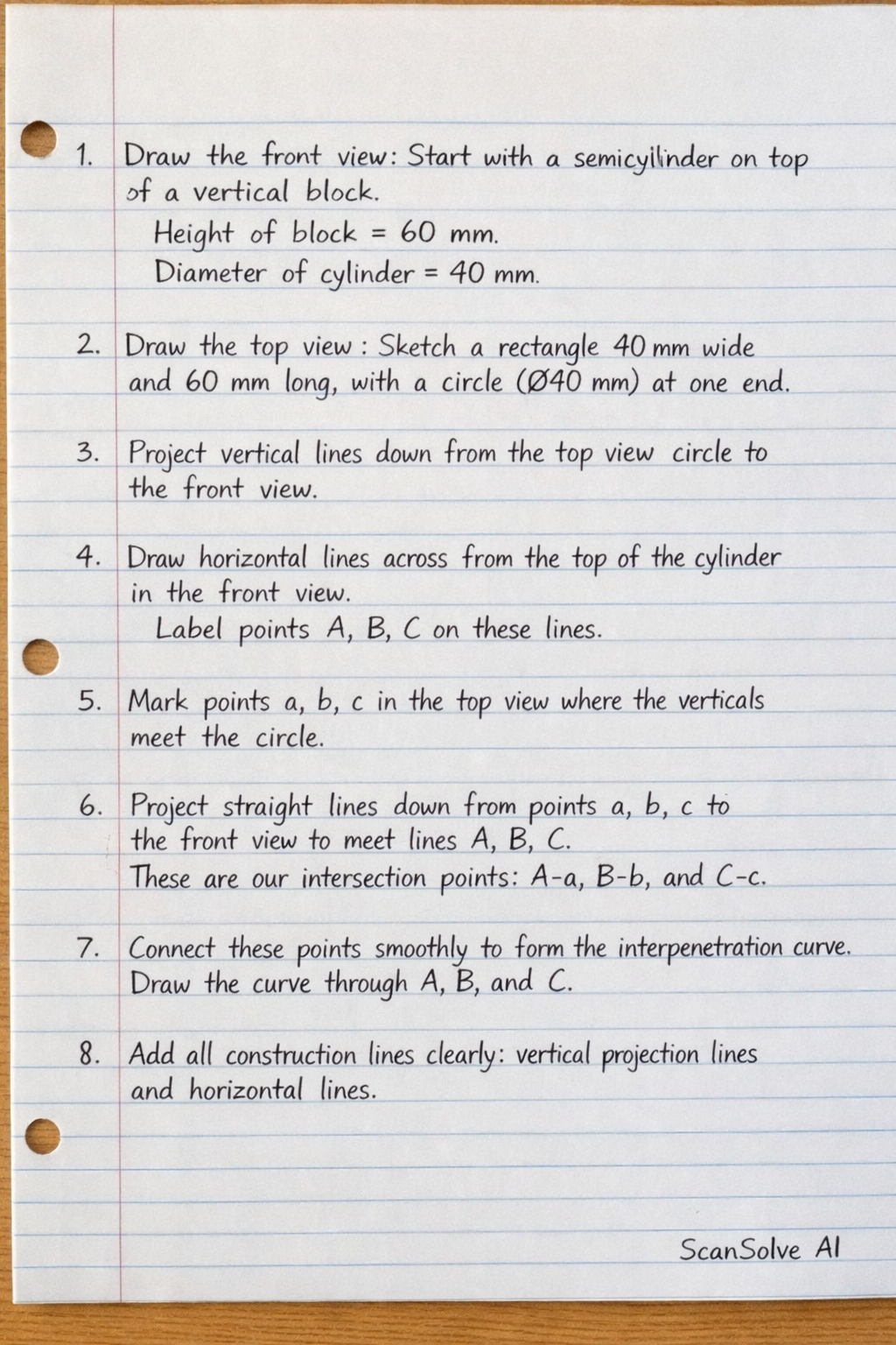
This problem requires a technical drawing solution, which I cannot directly produce as an image. However, I can provide a detailed, step-by-step explanation of how to construct the drawing and the interpenetration curve, including all necessary construction lines. Understanding the Problem: The problem asks to redraw two views of a T-end and then show the curve of interpenetration on the front view, along with all construction lines. The key to an interpenetration curve is usually a cylinder intersecting a non-flat surface. From the given views: Front View: Shows a T-shaped object. Overall width: 130 mm Overall height: 72 mm Base height: 25 mm The stem of the T-shape is centered. Its width is not directly given in the front view, but the top view implies a thickness of 50 mm for the main body. Therefore, the stem width is 50 mm. The stem extends from x = (130-50)/(2) = 40 mm to x = 40+50 = 90 mm (from the left edge). The R30 fillets connect the stem to the top bar. These are internal curves. Center for the left R30 fillet: (40+30, 72-30) = (70, 42) mm. Center for the right R30 fillet: (90-30, 72-30) = (60, 42) mm. Top View: Shows the plan view of the T-end. Overall length: 130 mm (matches front view width) Overall width: 50 mm (derived from 2 × R25 at the ends of the slot, which defines the thickness of the T-end). There is a central 50 circle. This circle represents the end view of the intersecting cylinder*. This means the cylinder's axis is horizontal and parallel to the front view. The cylinder is centered in the top view, so its axis is at x = (130)/(2) = 65 mm and y = (50)/(2) = 25 mm (relative to the top view's origin). Interpretation for Interpenetration: The 50 circle in the top view is the end profile of a cylinder that passes through the T-end. Its axis is horizontal and parallel to the front view. In the front view, the cylinder's axis will be a horizontal line at x=65 mm (center of the T-end). The vertical position of the cylinder's axis is not explicitly given. A common assumption is that it's centered vertically within the stem of the T-end. The stem's height is 72 - 25 = 47 mm. So, the cylinder's axis would be at y = 25 + (47)/(2) = 25 + 23.5 = 48.5 mm from the bottom of the front view. The cylinder has a diameter of 50 mm, so its radius is 25 mm. The cylinder's top surface will be at y = 48.5 + 25 = 73.5 mm. The cylinder's bottom surface will be at y = 48.5 - 25 = 23.5 mm. The cylinder passes through the thickness of the T-end, which is 50 mm (from the top view). The interpenetration curve will be formed where the 50 cylinder intersects the R30 fillets of the T-end. --- Step-by-Step Construction: Step 1: Redraw the Given Views (Scale 1:1) Draw the Front View of the T-end: Draw a horizontal line 130 mm long for the base. Draw vertical lines 25 mm high at both ends of the base. Connect their tops with a horizontal line. From the center of the 130 mm base, measure 25 mm to the left and 25 mm to the right to define the 50 mm wide stem. Draw vertical lines upwards from these points (x=40 and x=90) to the total height of 72 mm. Draw the top horizontal line of the T-bar, 130 mm long, at y=72 mm. Draw the R30 fillets: For the left fillet, locate the center at (70, 42) mm. Draw an arc with radius 30 mm connecting the vertical edge of the stem (x=40) to the underside of the top bar (y=72). For the right fillet, locate the center at (60, 42) mm. Draw an arc with radius 30 mm connecting the vertical edge of the stem (x=90) to the underside of the top bar (y=72). Draw the Top View of the T-end: Draw a rectangle 130 mm long and 50 mm wide. At each end of the 130 mm length, draw semicircles with radius R25 to form the rounded ends of the slotted shape. Draw the centerlines for the 50 cylinder: a horizontal line at y=25 mm and a vertical line at x=65 mm (relative to the top view's origin). Draw the 50 circle, centered at the intersection of these centerlines. This represents the end view of the intersecting cylinder. Step 2: Project Construction Lines from Top View to Front View Divide the 50 circle in the Top View into 12 or 16 equal parts (e.g., every 30^ or 22.5^). Label these points (e.g., P_1, P_2, , P_12). From each of these points on the 50 circle, draw horizontal projection lines across the top view. These lines represent elements on the surface of the cylinder. From each of these points on the 50 circle, project vertical construction lines downwards towards the Front View. These lines will define the horizontal positions of points on the interpenetration curve. In the Front View, draw the horizontal axis of the cylinder at y=48.5 mm. Draw the vertical center line of the T-end at x=65 mm. Step 3: Determine Depths and Locate Points on the Interpenetration Curve The interpenetration curve occurs where the cylinder intersects the R30 fillets. For each horizontal projection line from the top view (representing an element on the cylinder's surface), measure its distance from the cylinder's axis in the top view. This distance represents the "depth" or "offset" of that element from the cylinder's central plane. In the front view, for each vertical projection line from the top view: Locate the corresponding point on the cylinder's circumference. The cylinder's profile in the front view is a rectangle of width 50 mm (from x=40 to x=90) and height 50 mm (from y=23.5 to y=73.5). The curve will be formed by points where the cylinder's surface meets the R30 fillets. Consider a point P_i on the 50 circle in the top view. Its horizontal projection line gives its depth from the cylinder's axis. Project P_i vertically down to the front view. This gives an x-coordinate. The y-coordinate for the interpenetration curve point will be found by intersecting the cylinder's surface with the T-end's surface. Since the cylinder's axis is at y=48.5 and its radius is 25, its equation in the front view (for the curved part) is (y-48.5)^2 + z^2 = 25^2, where z is the depth from the center plane of the cylinder. The R30 fillets are defined by (x-70)^2 + (y-42)^2 = 30^2 (left) and (x-60)^2 + (y-42)^2 = 30^2 (right). For each projected vertical line from the top view (which gives an x-coordinate in the front view), find the corresponding y-coordinate on the R30 fillet. For example, take a point P_k on the 50 circle. Its vertical projection gives an x-value. Its horizontal projection gives a z-value (distance from the center of the 50 circle). In the front view, for that x-value, find the y-value on the R30 fillet. Then, from the cylinder's axis (y=48.5), measure z upwards and downwards to find two points on the cylinder's surface. The interpenetration curve points are where these cylinder surface points coincide with the T-end's surface. Specifically, for each vertical projection line from the top view (which gives an x-coordinate in the front view), measure the corresponding y-coordinate on the R30 fillet. This y-coordinate is a point on the T-end's surface. Now, for the same x-coordinate, find the y-coordinate on the cylinder's surface. The cylinder's surface is defined by y_cyl = 48.5 ± sqrt(25^2 - z^2), where z is the horizontal distance from the cylinder's center line (x=65) in the top view. The points of interpenetration are where y_fillet = y_cyl. This is a graphical process. For each vertical projection line from the top view (e.g., from P_1, P_2, ), measure the horizontal distance from the center line of the cylinder in the top view. Let this be d. In the front view, for the same vertical projection line, measure d horizontally from the cylinder's axis (y=48.5). This gives points on the cylinder's profile. The curve will be formed by connecting the points where the cylinder's profile intersects the R30 fillets. Step 4: Draw the Interpenetration Curve Connect the located points in the front view with a smooth curve. This curve will be symmetrical about the vertical center line (x=65 mm). The curve will start at the points where the cylinder's top/bottom surfaces intersect the vertical edges of the stem, and extend inwards to meet the R30 fillets. The curve will be visible on both the left and right sides of the stem where the cylinder passes through the R30 fillets. Step 5: Show All Construction Lines Ensure all projection lines from the top view to the front view are visible. Show the division of the 50 circle in the top view. Show the horizontal lines from these divisions in the top view. Show the vertical projection lines from the top view to the front view. Show the horizontal axis of the cylinder in the front view. Show the center lines for both views. The final drawing will show the T-end with a smooth, symmetrical curve on its front view, representing the intersection of the 50 cylinder with the R30 fillets. Since I cannot draw the solution, the description above outlines the precise steps you would take with drafting tools. Send me the next one 📸