
This computer science problem involves algorithmic thinking and programming concepts. The solution below explains the approach, logic, and implementation step by step.
ScanSolve AI Answer
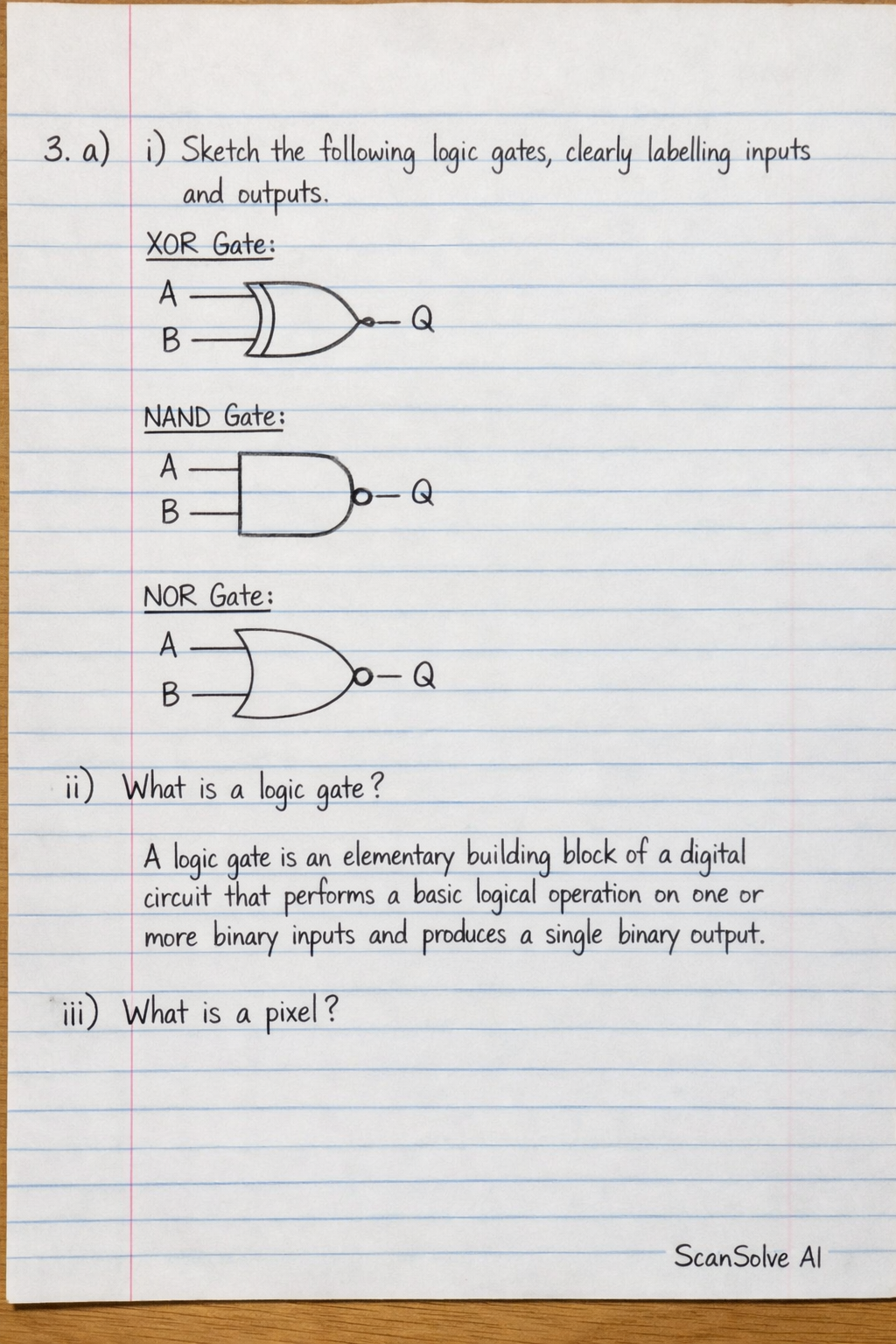
3. a) i) Sketch the following logic gates, clearly labelling inputs and outputs XOR Gate: [scale=0.8, transform shape] (0,0) node[xor gate, draw, logic external ports=left, logic gate inputs=A and B, logic gate outputs=Q] ; NAND Gate: [scale=0.8, transform shape] (0,0) node[nand gate, draw, logic external ports=left, logic gate inputs=A and B, logic gate outputs=Q] ; NOR Gate: [scale=0.8, transform shape] (0,0) node[nor gate, draw, logic external ports=left, logic gate inputs=A and B, logic gate outputs=Q] ; ii) What is a logic gate? A logic gate is an elementary building block of a digital circuit that performs a basic logical operation on one or more binary inputs and produces a single binary output. iii) What is a pixel? A pixel (short for "picture element") is the smallest individual unit of a digital image or display that can be assigned a color and displayed. It is the fundamental component of all images shown on a screen. b) The question is incomplete as the specific tasks or questions related to Figure 1 and Figure 2 are not visible in the provided image.