
We read your photo as:
This image shows a wiring diagram for a "STAR DELTA AUTO & PB STARTER". What is the function of each labeled component?
Computer Science
ScanSolve AI Answer
Step-by-step solution
10 stepsHere are the steps for wiring a Star Delta Starter, using the components and connections visible in your provided image:
Power Circuit Wiring:
Main Power Input and Protection
- Connect the 3-phase incoming supply (L1, L2, L3) from the 3-Phase Supply Input (2) to the input terminals of the Main Switch (Isolator) (1).
- Connect the output terminals of the Main Switch (Isolator) (1) to the input terminals of the Control Circuit MCB (Fuses) (3).
- Connect the Earth (Green wire) from the 3-Phase Supply Input (2) to the motor's earth terminal.
Main Contactor (4) and Overload Relay (7)
- Connect the 3-phase output (L1, L2, L3) from the Control Circuit MCB (3) to the input terminals (L1, L2, L3) of the Main Contactor (4).
- Connect the output terminals (T1, T2, T3) of the Main Contactor (4) to the input terminals (L1, L2, L3) of the Overload Relay (7).
- Connect the output terminals (T1, T2, T3) of the Overload Relay (7) to the primary motor terminals (U1, V1, W1) of the 3-Phase Induction Motor (13). (Red to U1, Yellow to V1, Blue to W1).
Star Contactor (5) and Motor Secondary Windings
- Connect the secondary motor terminals (U2, V2, W2) of the 3-Phase Induction Motor (13) to the input terminals (L1, L2, L3) of the Star Contactor (5). (Red to U2, Yellow to V2, Blue to W2).
- Short-circuit the output terminals (T1, T2, T3) of the Star Contactor (5) together to form the star point.
Delta Contactor (6) and Motor Secondary Windings
- Take a 3-phase supply directly from the output of the Control Circuit MCB (3) (L1, L2, L3) and connect it to the input terminals (L1, L2, L3) of the Delta Contactor (6).
- Connect the output terminals (T1, T2, T3) of the Delta Contactor (6) to the secondary motor terminals (U2, V2, W2) of the 3-Phase Induction Motor (13) with the following cross-connections:
- Delta Contactor output T1 (Red wire) to motor terminal W2.
- Delta Contactor output T2 (Yellow wire) to motor terminal U2.
- Delta Contactor output T3 (Blue wire) to motor terminal V2.
Control Circuit Wiring:
Control Circuit Power Supply and Overload Protection
- Take a single-phase supply (L1 - Red wire) from the output of the Control Circuit MCB (3) for the control circuit.
- Connect this control supply through the normally closed (NC) auxiliary contact of the Overload Relay (7) (terminals O/L-1, typically 95-96).
STOP Push Button (8) and START Push Button (9)
- From the output of the Overload Relay NC contact (terminal 96), connect to the input of the STOP Push Button (8) (NC contact, terminal 1).
- From the output of the STOP Push Button (8) (NC contact, terminal 2), connect to the input of the START-1 Push Button (9) (NO contact, terminal 3).
Main Contactor (4) Coil and Holding Circuit
- From the output of the START-1 Push Button (9) (NO contact, terminal 4), connect to the A1 terminal of the Main Contactor (4) coil.
- Wire a normally open (NO) auxiliary contact of the Main Contactor (4) (e.g., terminals 13NO-14) in parallel with the START-1 Push Button (9). Connect one side (13NO) to the output of the STOP Push Button (8) (terminal 2) and the other side (14) to the A1 terminal of the Main Contactor (4) coil.
Timer Relay (12) and Star Contactor (5) Coil Circuit
- From the A1 terminal of the Main Contactor (4) coil, connect to the A1 terminal of the Timer Relay (12) coil.
- Also from the A1 terminal of the Main Contactor (4) coil, connect through a normally closed (NC) auxiliary contact of the Timer Relay (12) (e.g., 15-16) and then through a normally closed (NC) auxiliary contact of the Delta Contactor (6) (e.g., 21NC-22) to the A1 terminal of the Star Contactor (5) coil.
Delta Contactor (6) Coil Circuit
- From the A1 terminal of the Main Contactor (4) coil, connect through a normally open (NO) auxiliary contact of the Timer Relay (12) (e.g., 15-18) and then through a normally closed (NC) auxiliary contact of the Star Contactor (5) (e.g., 21NC-22) to the A1 terminal of the Delta Contactor (6) coil.
Neutral Connections
- Connect the A2 terminals of the Main Contactor (4), Star Contactor (5), Delta Contactor (6), and Timer Relay (12) coils to the Neutral (N) line (Black wire) from the 3-Phase Supply Input (2).
Was this helpful?
Still stuck on this one?
Ask a follow-up, and the answer starts from this question.
Got a different question?Ask your own question
More Computer Science Questions
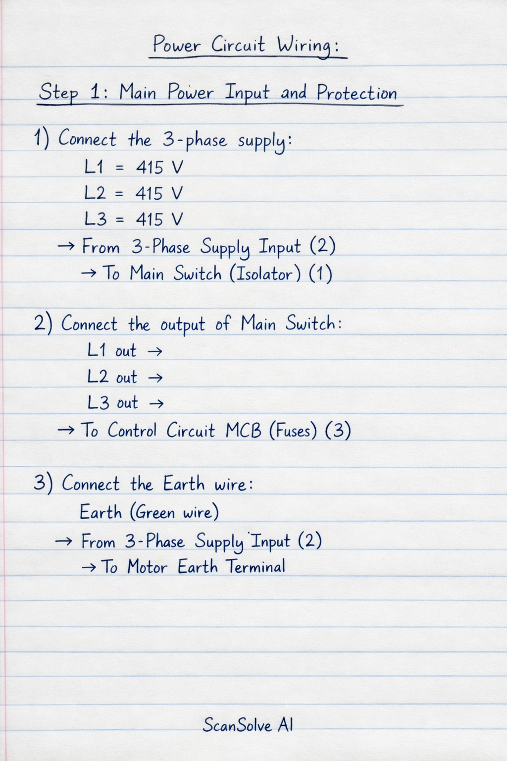
Handwritten Step-by-Step Solution
Get this as a handwritten image on WhatsApp — like a tutor wrote it for you.
Try on WhatsApp