
We read your photo as:
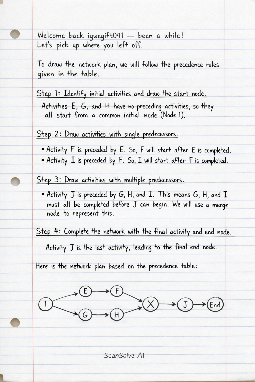
Consider the following precedence table and draw the network planv
Computer Science
ScanSolve AI Answer
Answer
Step-by-step solution
4 stepsTo draw the network plan, we will follow the precedence rules given in the table.
Identify initial activities and draw the start node.
Activities E, G, and H have no preceding activities, so they all start from a common initial node (Node 1).
Draw activities with single predecessors.
- Activity F is preceded by E. So, F will start after E is completed.
- Activity I is preceded by F. So, I will start after F is completed.
Draw activities with multiple predecessors.
- Activity J is preceded by G, H, and I. This means G, H, and I must all be completed before J can begin. We will use a merge node to represent this.
Complete the network with the final activity and end node.
Activity J is the last activity, leading to the final end node.
Here is the network plan based on the precedence table:
\begin{tikzpicture}[node distance=2cm, auto, thick]
    % Nodes
    \node (start) [circle, draw] {1};
    \node (E_end) [circle, draw, right of=start, xshift=1.5cm] {2};
    \node (G_end) [circle, draw, below right of=start, yshift=0.5cm, xshift=0.5cm] {3};
    \node (H_end) [circle, draw, below right of=start, yshift=-0.5cm, xshift=0.5cm] {4};
    \node (F_end) [circle, draw, right of=E_end, xshift=1.5cm] {5};
    \node (I_end) [circle, draw, right of=F_end, xshift=1.5cm] {6};
    \node (J_start) [circle, draw, below right of=I_end, yshift=-1.5cm, xshift=-1.5cm] {7}; % Merge node for G, H, I
    \node (end) [circle, draw, right of=J_start, xshift=1.5cm] {8};

    % Edges (Activities)
    \draw[->] (start) -- node {E} (E_end);
    \draw[->] (start) -- node {G} (G_end);
    \draw[->] (start) -- node {H} (H_end);

    \draw[->] (E_end) -- node {F} (F_end);
    \draw[->] (F_end) -- node {I} (I_end);

    % Merge for J
    \draw[->] (G_end) -- (J_start);
    \draw[->] (H_end) -- (J_start);
    \draw[->] (I_end) -- (J_start);

    \draw[->] (J_start) -- node {J} (end);
\end{tikzpicture}
The network plan is shown above.
See diagram above
Was this helpful?
Try one yourself
A new problem that tests the same skill.
Still stuck on this one?
Ask a follow-up, and the answer starts from this question.
Got a different question?Ask your own question
More Computer Science Questions
Handwritten Step-by-Step Solution
Get this as a handwritten image on WhatsApp — like a tutor wrote it for you.
Try on WhatsApp