
This computer science problem involves algorithmic thinking and programming concepts. The solution below explains the approach, logic, and implementation step by step.
ScanSolve AI Answer
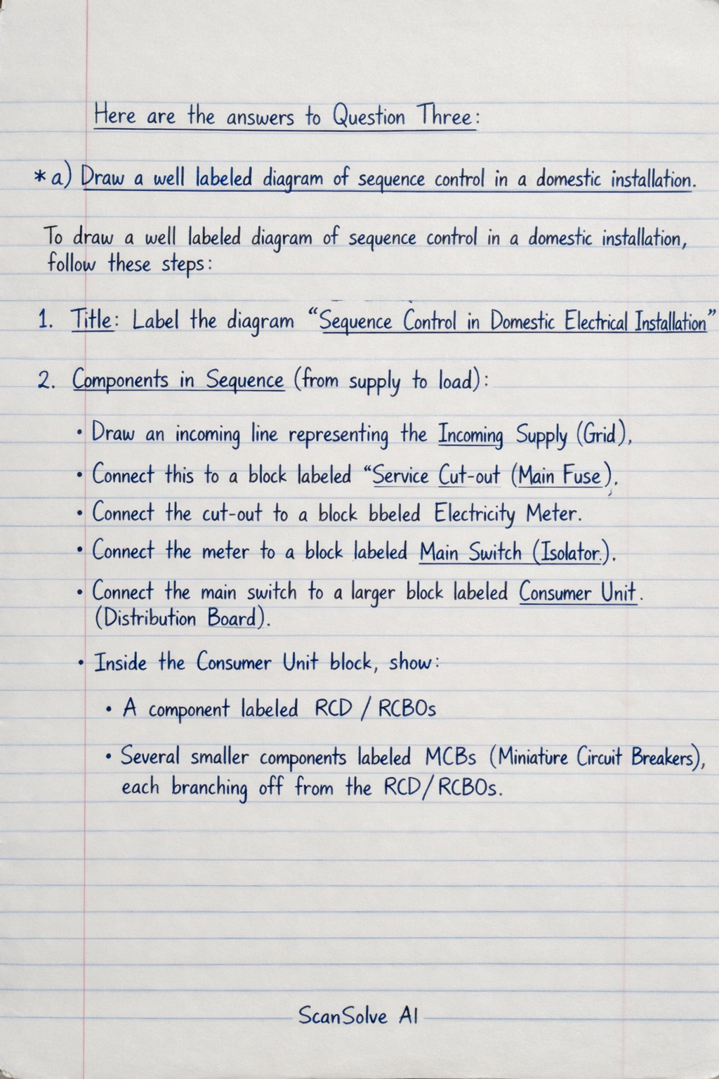
Here are the answers to Question Three: a) Draw a well labeled diagram of sequence control in a domestic installation. To draw a well-labeled diagram of sequence control in a domestic installation, follow these steps: 1. Title: Label the diagram "Sequence Control in Domestic Electrical Installation". 2. Components in Sequence (from supply to load): Draw an incoming line representing the Incoming Supply (Grid). Connect this to a block labeled Service Cut-out (Main Fuse). Connect the cut-out to a block labeled Electricity Meter. Connect the meter to a block labeled Main Switch (Isolator). Connect the main switch to a larger block labeled Consumer Unit (Distribution Board). Inside the Consumer Unit block, show: A component labeled RCD/RCBOs (Residual Current Devices/Residual Current Breakers with Overcurrent protection). Several smaller components labeled MCBs (Miniature Circuit Breakers), each branching off from the RCD/RCBOs. From each MCB, draw lines extending outwards, representing Final Circuits. Label these with examples like "Lighting Circuit", "Socket Circuit", "Cooker Circuit". 3. Connections and Flow: Use arrows to indicate the direction of power flow from the Incoming Supply through each component to the Final Circuits. 4. Earthing: Draw a separate line representing the Main Earthing Conductor connected to the Main Earthing Terminal (usually near the main switch or consumer unit). Show earth connections branching from the main earthing terminal to the consumer unit and then to each final circuit. b) Describe three essential points in consumer's installation as required by the IEE regulations. Here are three essential points in a consumer's electrical installation as required by the IEE Wiring Regulations (now BS 7671): 1. Protection against Electric Shock: The installation must incorporate measures to prevent electric shock, such as earthing and bonding of all exposed conductive parts, and the use of Residual Current Devices (RCDs) for additional protection on specific circuits (e.g., socket outlets, lighting in bathrooms). 2. Protection against Overcurrent: All circuits must be protected by appropriate overcurrent protective devices (fuses or Miniature Circuit Breakers - MCBs) to prevent damage to cables and equipment from overload or short-circuit currents. The rating of these devices must be correctly matched to the current-carrying capacity of the associated cables. 3. Isolation and Switching: Adequate means of isolation must be provided to safely disconnect the entire installation or individual circuits for maintenance, repair, or in an emergency. This typically includes a main switch at the consumer unit and local switches for appliances and lighting points. c) Draw the wiring diagram of one lighting point controlled from two different locations through a joint box. To draw the wiring diagram for two-way switching with a joint box, follow these steps: 1. Title: Label the diagram "Two-Way Switching with Joint Box". 2. Components: Draw the Supply (Live/Phase, Neutral, Earth conductors). Draw a rectangular box labeled Joint Box. Draw two Two-Way Switches, labeled "Switch 1" and "Switch 2". Each switch should have three terminals: one common terminal and two switched terminals (often labeled L1, L2, L3 or C, 1, 2). Draw a Lamp Holder with terminals for Live (switched phase) and Neutral. 3. Connections (using standard wire colors for clarity): Live (Phase) Connection: The incoming Brown* Live conductor from the supply enters the Joint Box. From the Joint Box, a Brown* wire connects to the Common terminal of Switch 1. Traveler Wires (Strappers): Two wires (e.g., Grey and Black*) connect the two switched terminals of Switch 1 to the corresponding two switched terminals of Switch 2. These two wires should pass through the Joint Box. Switched Live to Lamp: From the Common terminal of Switch 2, a Brown* wire (switched live) goes into the Joint Box. From the Joint Box, this Brown* wire connects to the Live terminal of the Lamp Holder. Neutral Connection: The incoming Blue* Neutral conductor from the supply enters the Joint Box. From the Joint Box, a Blue* wire connects to the Neutral terminal of the Lamp Holder. Earth Connection: The incoming Green/Yellow* Earth conductor from the supply enters the Joint Box. From the Joint Box, Green/Yellow* wires connect to the earth terminals of Switch 1, Switch 2, and the Lamp Holder (if metallic). All earth wires must be connected together within the joint box. 4. Labels: Ensure all components (Supply, Joint Box, Switch 1, Switch 2, Lamp Holder) and all conductors (Live, Neutral, Earth, Travelers, Switched Live) are clearly labeled.