
We read your photo as:
Star Delta Auto & PB Starter
Computer Science
ScanSolve AI Answer
here are the explanations for the components in the Star-Delta starter diagram:
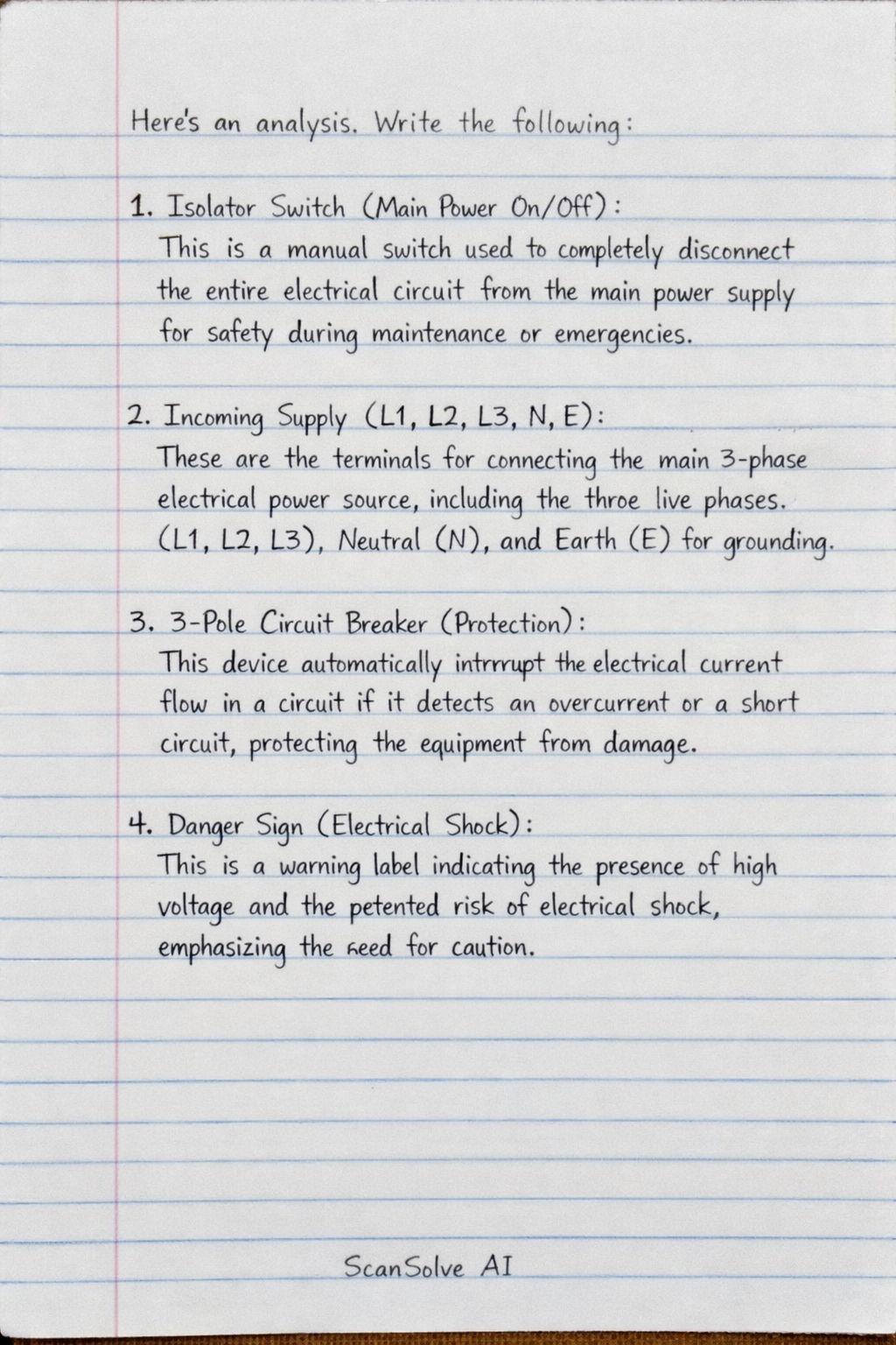
- ISOLATOR SWITCH (Main Power On/Off): This is a manual switch used to completely disconnect the entire electrical circuit from the main power supply for safety during maintenance or emergencies.
- INCOMING SUPPLY (L1, L2, L3, N, E): These are the terminals for connecting the main 3-phase electrical power source, including the three live phases (L1, L2, L3), Neutral (N), and Earth (E) for grounding.
- 3-POLE CIRCUIT BREAKER (Protection): This device automatically interrupts the electrical current flow in a circuit if it detects an overcurrent or a short circuit, protecting the equipment from damage.
- DANGER SIGN (Electrical Shock): This is a warning label indicating the presence of high voltage and the potential risk of electrical shock, emphasizing the need for caution.
- STAR CONTACTOR (KM1): This magnetic switch is responsible for connecting the motor windings in a star configuration during the initial starting period. This reduces the starting current and torque.
- MAIN CONTACTOR (KM2): This is the primary magnetic switch that connects the motor to the main power supply. It remains closed throughout both the star and delta operating modes.
- (The third contactor, not explicitly numbered but visible, is the DELTA CONTACTOR (KM3). It connects the motor windings in a delta configuration for normal, full-power operation after the star starting phase.)
- ON-DELAY TIMER (TIMER): This device provides a set time delay. In a star-delta starter, it controls the transition from the star configuration to the delta configuration after a predetermined period.
- OVERLOAD RELAY (OL): This protective device monitors the current drawn by the motor. If the current exceeds a safe limit for too long, it trips to disconnect the motor, preventing overheating and damage.
- CONTROL PUSH BUTTONS (STOP, START-1, STOP-2, START-2): These are manual switches used to control the operation of the motor starter. The STOP buttons are normally closed (NC) and stop the motor, while the START buttons are normally open (NO) and initiate the motor's operation.
- AUXILIARY TERMINALS: These are additional connection points, typically used for wiring control circuits, indicator lights, or other external control devices.
- THERMAL OVERLOAD RESET (Manual Reset): This is a button or lever on the overload relay that allows an operator to manually reset the relay after it has tripped due to an overload condition.
- MOTOR TERMINALS (U1, V1, W1, U2, V2, W2): These are the connection points on the 3-phase induction motor where the power cables from the starter are connected. U1, V1, W1 are the start of the windings, and U2, V2, W2 are the end of the windings, allowing for different connection configurations (star or delta).
- 3-PHASE INDUCTION MOTOR: This is the electrical machine that converts electrical energy into mechanical energy, providing the power to drive machinery. It is the load controlled by the star-delta starter.
Was this helpful?
Still stuck on this one?
Ask a follow-up, and the answer starts from this question.
Got a different question?Ask your own question
More Computer Science Questions
QIdentify all the components of the Star Delta Auto & PB Starter.QThis image shows a wiring diagram for a "STAR DELTA AUTO & PB STARTER". What is the function of each…QAUTOMATIC AUTO-TRANSFORMER STARTERQWhat are steps how to wiring a Star Delta StarterQDraw the power diagram of the star Delta starter two directions of control
Handwritten Step-by-Step Solution
Get this as a handwritten image on WhatsApp — like a tutor wrote it for you.
Try on WhatsApp