
We read your photo as:
Draw a circuit diagram and include the following electronic components: 6v battery, switch/switches, transistor, resistor.
Computer Science
ScanSolve AI Answer
Here is the circuit diagram including the specified components:
\begin{circuitikz} \draw
(0,0) to[battery1, l_=$6V$] (0,4)
(0,4) -- (2,4) to[switch] (4,4) to[R, l_=$R_B$] (6,4)
(6,4) -- (6,3) node[npn, anchor=base] (Q1) {}
(Q1.collector) -- (6,5) -- (2,5) -- (2,4)
(Q1.emitter) -- (6,1) -- (0,1) -- (0,0)
;
\end{circuitikz}
This circuit diagram shows:
- A 6V battery providing power.
- A switch connected in series with a resistor ().
- An NPN transistor (Q1) with its base connected to the resistor, its collector connected to the positive terminal of the battery, and its emitter connected to the negative terminal of the battery.
This configuration represents a basic transistor switching circuit where the switch controls the base current, which in turn controls the transistor's collector current. The resistor is a base current limiting resistor.
Was this helpful?
Still stuck on this one?
Ask a follow-up, and the answer starts from this question.
Got a different question?Ask your own question
More Computer Science Questions
QDraw a circuit diagram for a simple series circuit that includes a battery, a switch, and a…QDraw a circuit diagram showing a battery, a switch, and a light bulb. Show how to connect them to…QDraw a circuit diagram for a simple circuit containing a battery, a switch, a resistor, an ammeter…QDraw the circuit diagram.QDraw the symbol representing each component: 1.1 Cell 1.2 Battery 1.3 Resistor 1.4 Light bulb 1.5…
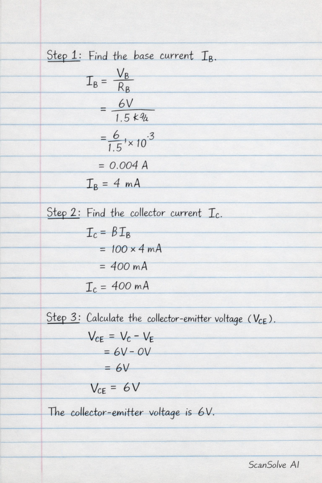
Handwritten Step-by-Step Solution
Get this as a handwritten image on WhatsApp — like a tutor wrote it for you.
Try on WhatsApp