
We read your photo as:
Draw a circuit diagram for a simple series circuit that includes a battery, a switch, and a resistor. Label the components.
ScanSolve AI Answer
Here's how to determine the "lost volt":
Diagram (2 marks)
\text{
    \begin{tikzpicture}[
        thick,
        battery/.pic={
            \draw (0,0) -- (0,0.5);
            \draw (0.2,0) -- (0.2,0.5);
            \draw (0.1,0.5) -- (0.1,0.7);
            \draw (0.1,0) -- (0.1,-0.2);
            \node at (0.1,0.8) {$+$};
            \node at (0.1,-0.3) {$-$};
        },
        resistor/.pic={
            \draw (0,0) -- (0.2,0) -- (0.3,0.2) -- (0.5,-0.2) -- (0.7,0.2) -- (0.9,-0.2) -- (1,0) -- (1.2,0);
        },
        switch/.pic={
            \draw (0,0) -- (0.2,0);
            \draw (0.2,0) circle (0.05);
            \draw (0.5,0.3) circle (0.05);
            \draw (0.2,0) -- (0.5,0.3);
            \draw (0.5,0.3) -- (0.7,0.3);
        },
        voltmeter/.pic={
            \draw (0,0) circle (0.3);
            \node at (0,0) {V};
        }
    ]
        % Main circuit components
        \coordinate (A) at (0,0);
        \coordinate (B) at (4,0);
        \coordinate (C) at (4,2);
        \coordinate (D) at (0,2);

        \draw (A) -- (B) -- (C) -- (D) -- cycle;

        % Battery
        \pic at (0.5,0) {battery};
        \node at (0.8, -0.5) {Battery};

        % Resistor
        \pic at (2.5,0) {resistor};
        \node at (3.1, -0.5) {Resistor (R)};

        % Switch
        \pic at (1.5,2) {switch};
        \node at (1.8, 2.5) {Switch (S)};

        % Voltmeter (for EMF/TPD measurement)
        \pic at (2,1) {voltmeter};
        \draw (0.8,0.5) -- (2,1); % Connect to battery positive
        \draw (0.1,-0.2) -- (2,1); % Connect to battery negative
        \draw[dashed] (0.8,0.5) -- (0.8,0); % Path to battery
        \draw[dashed] (0.1,0) -- (0.1,-0.2); % Path to battery
        \node at (2, 1.5) {Voltmeter};
    \end{tikzpicture}
}
Method/Precaution (4 marks)
- Method:
- Set up the circuit as shown in the diagram, ensuring the voltmeter is connected in parallel across the battery terminals.
- With the switch open, record the voltmeter reading. This reading represents the electromotive force (EMF), , of the battery.
- Close the switch, allowing current to flow through the resistor. Record the new voltmeter reading across the battery terminals. This reading represents the terminal potential difference (TPD), .
- Calculate the "lost volt" by subtracting the TPD from the EMF: Lost volt .
- Precaution:
- Ensure all connections are tight to minimize contact resistance, which could affect voltage readings.
- Use a voltmeter with a high internal resistance to ensure it draws negligible current and accurately measures the potential difference.
- Avoid parallax error when reading the voltmeter scale to ensure accurate measurements.
Observation (2 marks)
When the switch is open, the voltmeter reads a higher value (EMF). When the switch is closed, the voltmeter reading drops to a lower value (TPD).
Inference/Conclusion (2 marks)
The difference between the EMF and the TPD is the "lost volt". This voltage is lost due to the potential drop across the internal resistance of the battery when current flows through the circuit. The lost volt is given by , where is the current flowing and is the internal resistance of the battery.
Still stuck on this one?
Ask a follow-up, and the answer starts from this question.
More Physics Questions
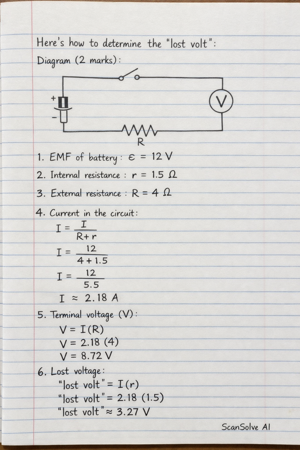
Handwritten Step-by-Step Solution
Get this as a handwritten image on WhatsApp — like a tutor wrote it for you.
Try on WhatsApp