
This physics problem tests your understanding of fundamental physical laws and their applications. The step-by-step solution below breaks down the problem using relevant equations and physical reasoning.
ScanSolve AI Answer
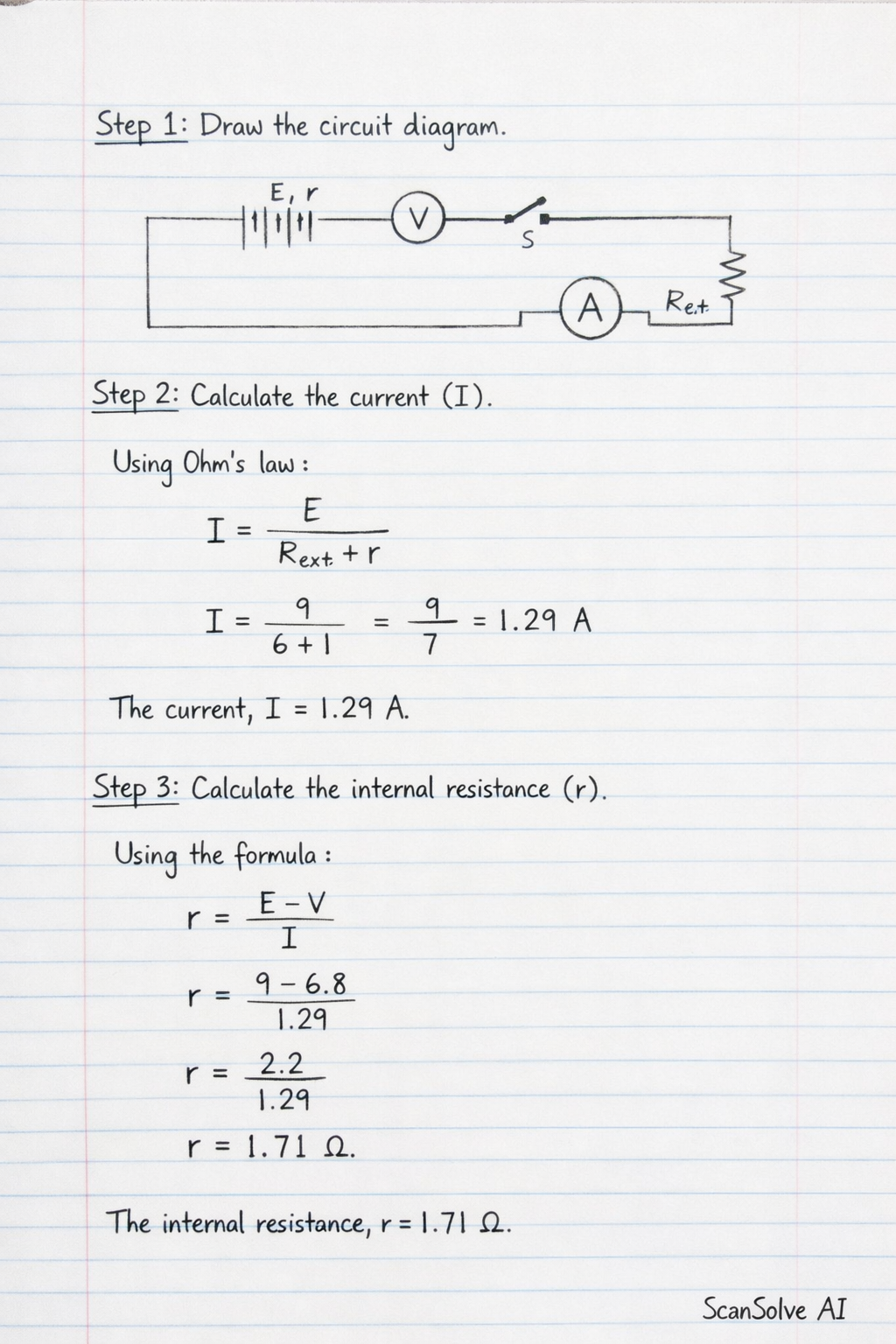
Step 1: Draw the circuit diagram. The circuit diagram for the experiment, as described and partially shown in the provided image, consists of: • A battery of three cells in series, representing the electromotive force (Emf) and internal resistance (r). • A voltmeter (V) connected in parallel across the terminals of the battery to measure the potential difference. • An ammeter (A) connected in series with the external circuit to measure the current (I). • A variable resistor (R_ext) connected in series with the ammeter. • An open switch (S) connected in series with the ammeter and variable resistor. [ circuit ee, scale=0.8, transform shape