
We read your photo as:
Draw the symbol representing each component: 1.1 Cell 1.2 Battery 1.3 Resistor 1.4 Light bulb 1.5 Open switch 1.6 Connecting wire 1.7 Ammeter 1.8 Voltmeter Study the circuit diagram and complete the tasks:
ScanSolve AI Answer
Step-by-step solution
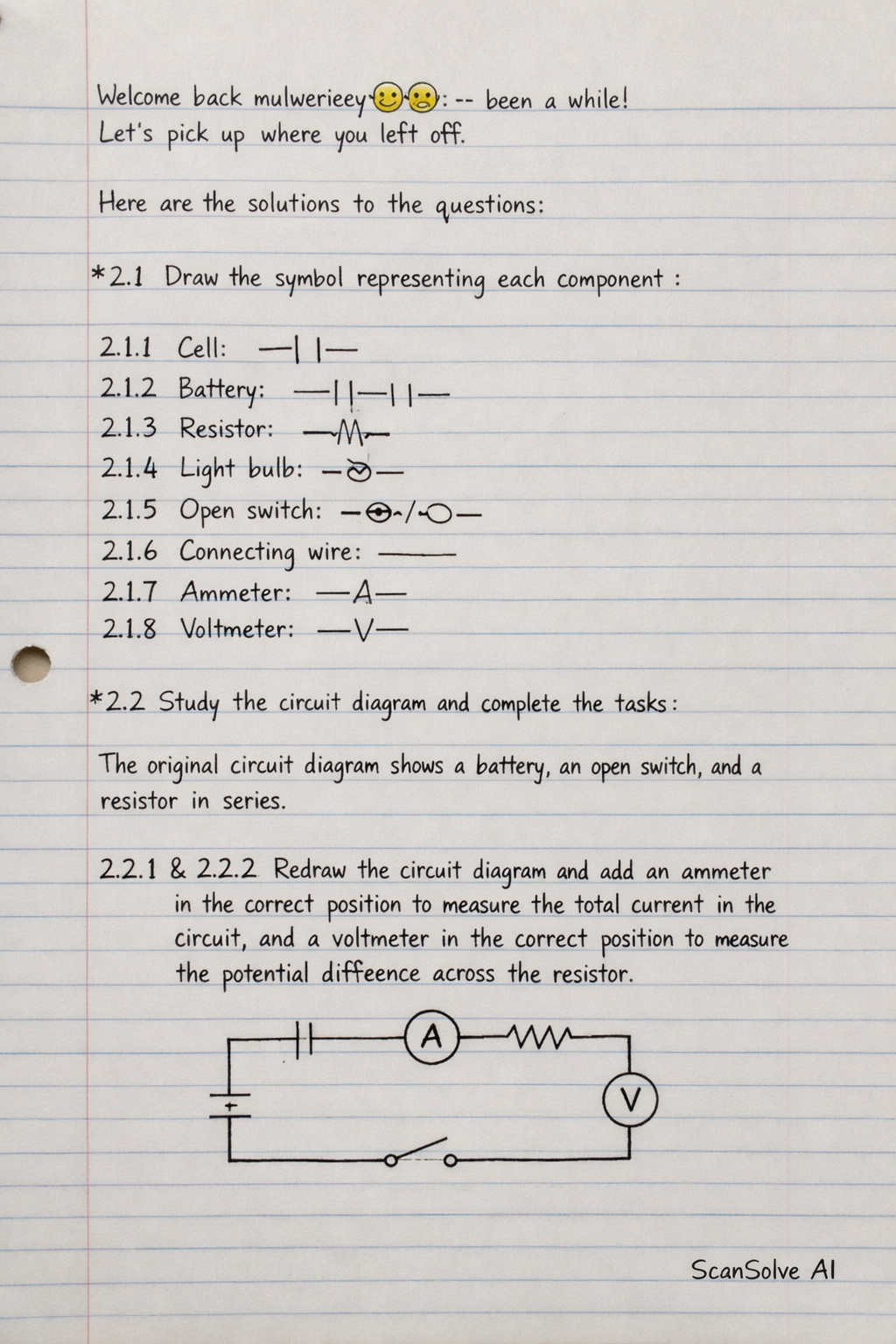
6 stepsHere are the solutions to the questions:
Part 2.1
Draw the symbol representing each component
2.1.1 Cell:
2.1.2 Battery:
2.1.3 Resistor:
2.1.4 Light bulb:
2.1.5 Open switch:
2.1.6 Connecting wire:
2.1.7 Ammeter:
2.1.8 Voltmeter:
Part 2.2· 3 steps
Study the circuit diagram and complete the tasks
The original circuit diagram shows a battery, an open switch, and a resistor in series.
2.2.1 and 2.2.2 Redraw the circuit diagram and add an ammeter in the correct position to measure the total current in the circuit, and a voltmeter in the correct position to measure the potential difference across the resistor.
Draw the original circuit components
battery, open switch, and resistor.
Add an ammeter in series with the other components to measure the total current.
Add a voltmeter in parallel across the resistor to measure the potential difference across it.
\begin{circuitikz} \draw
(0,0) to[battery] (0,2)
to[open switch] (2,2)
to[ammeter] (4,2)
to[R, l_=$R$] (4,0)
to (0,0)
(4,0) to[V, o-o] (4,2)
; \end{circuitikz}
Note: The diagram above represents the circuit with the ammeter in series and the voltmeter in parallel across the resistor.
Part 2.3· 3 steps
Study the circuit diagram
The circuit diagram shows a battery, an open switch, and three light bulbs connected in series.
2.3.1 Redesign and redraw the circuit diagram so that each bulb can be switched on and off independently. Use the same battery and bulbs, but you may add any additional components that are needed.
To allow each bulb to be switched on and off independently, they must be connected in parallel.
Each parallel branch containing a bulb needs its own switch.
Connect the parallel branches to the battery and a main switch.
\begin{circuitikz} \draw
(0,0) to[battery] (0,4)
to[open switch] (2,4)
to (4,4)
(4,4) to[open switch] (4,3) to[lamp] (4,2) to (4,0)
(4,4) to[open switch] (5,3) to[lamp] (5,2) to (5,0)
(4,4) to[open switch] (6,3) to[lamp] (6,2) to (6,0)
(4,0) to (6,0)
to (0,0)
; \end{circuitikz}
Note: The diagram above shows three light bulbs, each with its own switch, connected in parallel across the battery.
2.3.2 Identify the type of circuit you used in Question 2.3.1. Explain the reason for your choice.
The type of circuit used is a parallel circuit.
Reason: In a parallel circuit, each component (in this case, each light bulb) is connected across the same two points, meaning they have the same voltage across them. This allows each bulb to operate independently, as current can flow through each branch even if another branch is open (switched off). If one bulb burns out or is switched off, the others remain lit because their circuits are still complete.
Still stuck on this one?
Ask a follow-up, and the answer starts from this question.
More Physics Questions
Handwritten Step-by-Step Solution
Get this as a handwritten image on WhatsApp — like a tutor wrote it for you.
Try on WhatsApp