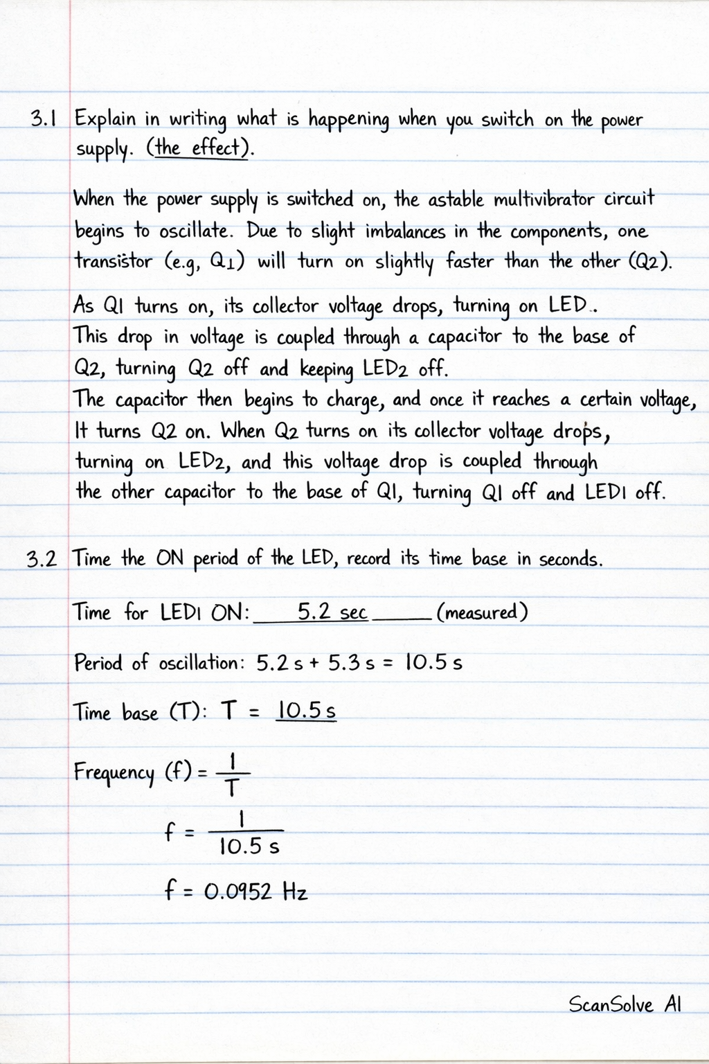
1 Explain in writing what is happening when you switch on the power supply. (the effect)

English
1 Explain in writing what is happening when you switch on the power supply. (the effect)

ScanSolve AI Answer

Answer

TON0.0693 sT_{ON} \approx \textbf{0.0693 s}

Here are the explanations for your astable multivibrator circuit:

3.1 Explain in writing what is happening when you switch on the power supply. (the effect)

When the power supply is switched on, the astable multivibrator circuit begins to oscillate. Due to slight imbalances in the components, one transistor (e.g., Q1) will turn on slightly faster than the other (Q2). As Q1 turns on, its collector voltage drops, turning on LED1. This drop in voltage is coupled through a capacitor to the base of Q2, turning Q2 off and keeping LED2 off. The capacitor then begins to charge, and once it reaches a certain voltage, it turns Q2 on. When Q2 turns on, its collector voltage drops, turning on LED2, and this voltage drop is coupled through the other capacitor to the base of Q1, turning Q1 off and LED1 off. This process continuously repeats, causing the two LEDs to blink alternately.

3.2 Time the ON period of the LED, record its time base in seconds.

This is an experimental measurement that needs to be performed with the actual circuit. To determine the ON period of one LED, you would use a stopwatch to measure the time one LED stays lit. For a symmetrical astable multivibrator, the ON period (or half-period) for each LED can be approximated by the formula: TON0.693×R×CT_{ON} \approx 0.693 \times R \times C Where RR is the base resistor value (e.g., 10 kΩ\Omega) and CC is the capacitor value (e.g., 10 μ\muF).

Using the component values from the previous circuit (R = 10 kΩ\Omega, C = 10 μ\muF): TON0.693×(10×103Ω)×(10×106F)T_{ON} \approx 0.693 \times (10 \times 10^3 \, \Omega) \times (10 \times 10^{-6} \, F) TON0.693×0.1sT_{ON} \approx 0.693 \times 0.1 \, s TON0.0693s\boxed{T_{ON} \approx 0.0693 s} Note: If the capacitors used were 50 μ\muF as mentioned in 3.3, then TON0.693×(10×103Ω)×(50×106F)0.3465sT_{ON} \approx 0.693 \times (10 \times 10^3 \, \Omega) \times (50 \times 10^{-6} \, F) \approx 0.3465 \, s. The actual measured value would depend on the exact components used.

3.3 Change the 50μ\muF capacitors with the 10nF capacitors. Explain in writing what is happening. (What is the effect?)

When the 50 μ\muF capacitors are replaced with 10 nF capacitors, the capacitance value is significantly reduced. The ON period and the total period of the astable multivibrator are directly proportional to the capacitance (TRCT \propto RC). Since the capacitance is much smaller (10 nF = 10×10910 \times 10^{-9} F, while 50 μ\muF = 50×10650 \times 10^{-6} F), the capacitors will charge and discharge much faster. The effect is that the blinking speed of the LEDs will increase dramatically. The LEDs will switch on and off at a much higher frequency. If the frequency becomes high enough, the individual blinks may no longer be distinguishable by the human eye, and the LEDs might appear to be continuously lit or flickering very rapidly.

3 done, 2 left today. You're making progress.

Was this helpful?

Need help with your own homework?

Get instant step-by-step solutions to any question. Free to start.

Ask Your Question
Handwritten step-by-step solution preview

Handwritten Step-by-Step Solution

Get this as a handwritten image on WhatsApp — like a tutor wrote it for you.

Try on WhatsApp

Still have questions?

Quick Answer

3.1 Explain in writing what is happening when you switch on the power supply. (the effect) When the power supply is switched on, the astable multivibrator circuit begins to oscillate.

1 Explain in writing what is happening when you switch on the power supply. (the effect)
English

This English question involves literary analysis, grammar, or writing skills. The detailed response below provides a well-structured answer with supporting evidence and clear explanations.

ScanSolve AI Answer
Here are the explanations for your astable multivibrator circuit: 3.1 Explain in writing what is happening when you switch on the power supply. (the effect) When the power supply is switched on, the astable multivibrator circuit begins to oscillate. Due to slight imbalances in the components, one transistor (e.g., Q1) will turn on slightly faster than the other (Q2). As Q1 turns on, its collector voltage drops, turning on LED1. This drop in voltage is coupled through a capacitor to the base of Q2, turning Q2 off and keeping LED2 off. The capacitor then begins to charge, and once it reaches a certain voltage, it turns Q2 on. When Q2 turns on, its collector voltage drops, turning on LED2, and this voltage drop is coupled through the other capacitor to the base of Q1, turning Q1 off and LED1 off. This process continuously repeats, causing the two LEDs to blink alternately. 3.2 Time the ON period of the LED, record its time base in seconds. This is an experimental measurement that needs to be performed with the actual circuit. To determine the ON period of one LED, you would use a stopwatch to measure the time one LED stays lit. For a symmetrical astable multivibrator, the ON period (or half-period) for each LED can be approximated by the formula: T_ON ≈ 0.693 × R × C Where R is the base resistor value (e.g., 10 k) and C is the capacitor value (e.g., 10 F). Using the component values from the previous circuit (R = 10 k, C = 10 F): T_ON ≈ 0.693 × (10 × 10^3 \, ) × (10 × 10^-6 \, F) T_ON ≈ 0.693 × 0.1 \, s T_ON ≈ 0.0693 s Note: If the capacitors used were 50 F as mentioned in 3.3, then T_ON ≈ 0.693 × (10 × 10^3 \, ) × (50 × 10^-6 \, F) ≈ 0.3465 \, s. The actual measured value would depend on the exact components used. 3.3 Change the 50F capacitors with the 10nF capacitors. Explain in writing what is happening. (What is the effect?) When the 50 F capacitors are replaced with 10 nF capacitors, the capacitance value is significantly reduced. The ON period and the total period of the astable multivibrator are directly proportional to the capacitance (T RC). Since the capacitance is much smaller (10 nF = 10 × 10^-9 F, while 50 F = 50 × 10^-6 F), the capacitors will charge and discharge much faster. The effect is that the blinking speed of the LEDs will increase dramatically. The LEDs will switch on and off at a much higher frequency. If the frequency becomes high enough, the individual blinks may no longer be distinguishable by the human eye, and the LEDs might appear to be continuously lit or flickering very rapidly. 3 done, 2 left today. You're making progress.