
We read your photo as:
A steel tube, 25 mm outside diameter and 12mm inside diameter, carries an axial tensile load of 40 kN. What will be the stress in the bar? What further increase in load is possible if the stress in the bar is limited to 225 MN/m?
ScanSolve AI Answer
This answer stops before the end.
It was cut off when it was first written. Ask ScanSolve this question again for the full working.
Okay, let's solve the mechanics questions from the image.
Question 3b) (Part 1 of 2)
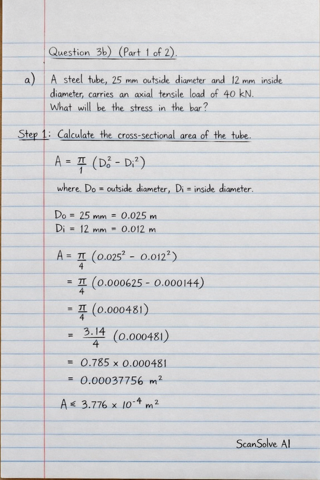
a) A steel tube, 25 mm outside diameter and 12mm inside diameter, carries an axial tensile load of 40 kN. What will be the stress in the bar?
Step 1: Calculate the cross-sectional area of the tube.
The area of a hollow tube is given by , where is the outside diameter and is the inside diameter.
Given: and .
Step 2: Calculate the stress in the bar.
Stress () is defined as force () per unit area ().
Given: .
b) What further increase in load is possible if the stress in the bar is limited to 225 MN/m²?
Step 3: Calculate the maximum possible load.
Given: Maximum allowable stress .
Step 4: Calculate the further increase in load.
Further increase in load () is the difference between the maximum possible load and the initial load.
Question 4a)
A beam AB, 1.2m long, is simply-supported at its ends A and B and carries two concentrated loads, one of 10 kN at C, the other 15 kN at D. Point C is 0.4m from A, point D is 1 m from A. Draw the S.F. and B.M. diagrams for the beam inserting principal values.
Step 1: Calculate reactions at supports A and B.
Let and be the reactions at A and B.
Total length .
Load at from A.
Load at from A.
Sum of vertical forces:
Sum of moments about A (clockwise positive):
Substitute into (1):
The reactions are: and .
Step 2: Calculate Shear Force (SF) values.
- (just right of A)
- (between A and C)
- (just right of C)
- (between C and D)
- (just right of D)
- (between D and B)
- (just left of B) (balanced by )
Step 3: Calculate Bending Moment (BM) values.
- (simply supported end)
- (at )
- (at )
- (simply supported end)
Question 4b)
A beam AB, 5 m long, is simply-supported at the end B and at a point C, 1 m from A. It carries vertical loads of 5 KN at A and 20kN at D, the center of the span BC. Draw S.F. and B.M. diagrams for the beam inserting principal values.
Step 1: Calculate reactions at supports C and B.
Beam length AB = 5 m.
Support C is at from A.
Support B is at from A.
Load at A ().
Span BC length = .
Load at D, center of span BC. So from A.
Let and be the reactions at C and B.
Sum of vertical forces:
Sum of moments about C (clockwise positive):
Substitute into (1):
The reactions are: and .
Step 2: Calculate Shear Force (SF) values.
- (just right of A) (downward load)
- (between A and C)
- (just right of C)
- (between C and D)
- (just right of D)
- (between D and B)
- (just left of B) (balanced by )
Step 3: Calculate Bending Moment (BM) values.
- (free end)
- (at ) (hogging)
- (at ) (sagging)
- (simply supported end)
Question 5)
A beam ABC is 9 m long and supported at B and C, 6 m apart as shown in Fig. 3.18. The beam carries a triangular distribution of load over the portion BC together with an applied counterclockwise couple of moment 80 KN m at Band a u.d.l. Of 10 KN/m over AB, as shown. Draw the S.F. and B.M. diagrams for the beam.
Note: The image provided only shows the diagram for Question 5, but the text for Question 5 is cut off. I will proceed with the information visible in the diagram and the partial text.
From the diagram:
- Beam length AC = 9 m.
- Support B is at 3 m from A.
- Support C is at 9 m from A (6 m from B).
- UDL of over AB (from to ).
- Counterclockwise couple of at B.
- Triangular load over BC (from to ). The load intensity at B is and decreases linearly to 0 at C.
Step 1: Calculate reactions at supports B and C.
Let and be the reactions at B and C.
Convert distributed loads to equivalent point loads:
- UDL over AB: . Acts at from A.
- Triangular load over BC: . This load acts at of the base from the higher end (B) or of the base from the zero end (C). So, it acts at from A.
Sum of vertical forces:
Sum of moments about B (clockwise positive):
Substitute into (1):
Still stuck on this one?
Ask a follow-up, and the answer starts from this question.
More Physics Questions
Handwritten Step-by-Step Solution
Get this as a handwritten image on WhatsApp — like a tutor wrote it for you.
Try on WhatsApp