An AM modulator has two inputs. The first input is a sine wave with a frequency of 500Hz and amplitude of 2V RMS. The second input is a carrier signal with RMS voltage of 4 V and frequency 1.5 MHz. Determine the equation for the modulated signal.
|Computer Science
An AM modulator has two inputs. The first input is a sine wave with a frequency of 500Hz and amplitude of 2V RMS. The second input is a carrier signal with RMS voltage of 4 V and frequency 1.5 MHz. Determine the equation for the modulated signal.
ScanSolve AI Answer
Answer
vAM(t)=42[1+0.5sin(1000πt)]sin(3×10⁶πt) V
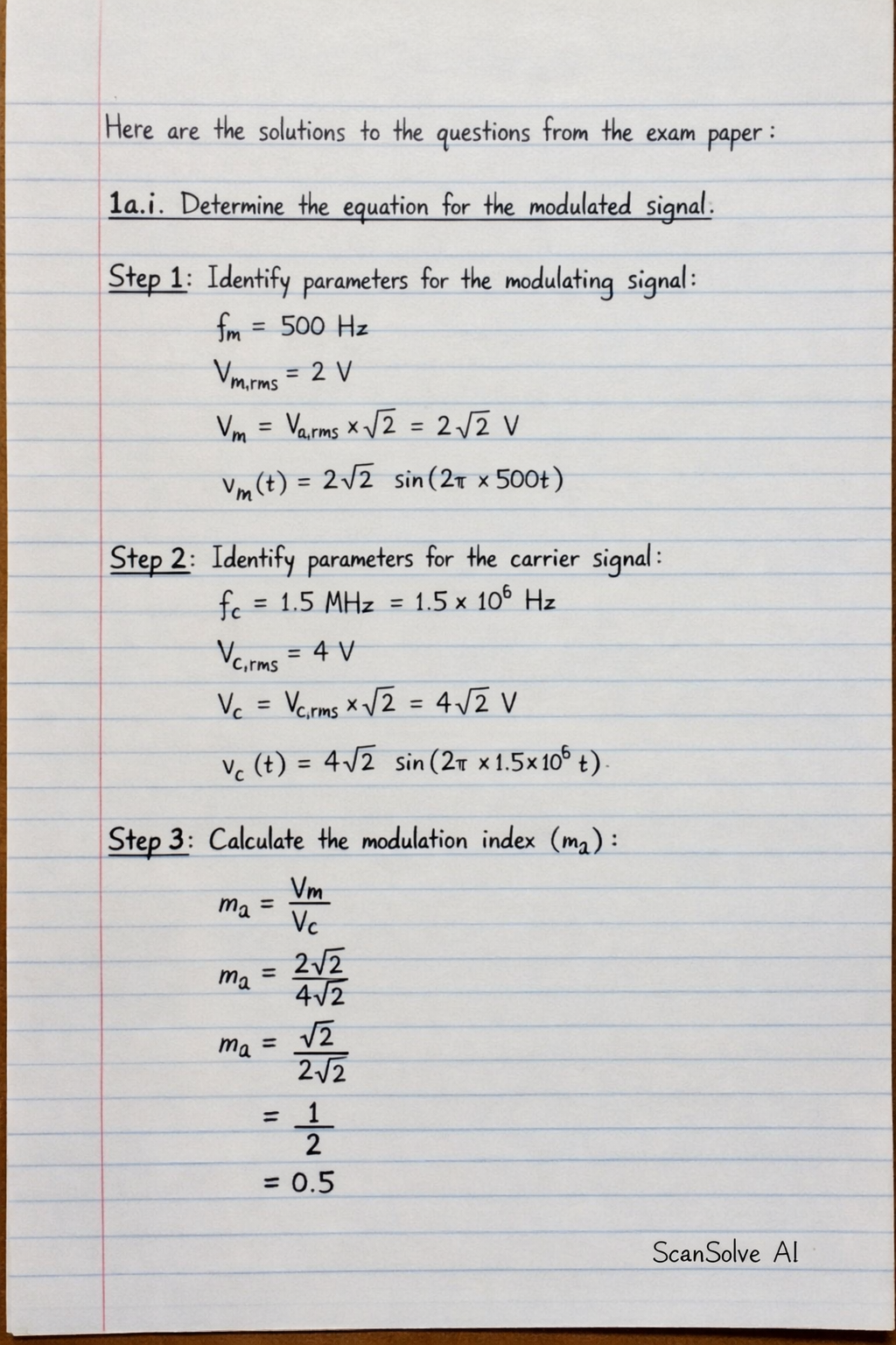
Here are the solutions to the questions from the exam paper:
1a.i. Determine the equation for the modulated signal.
Step 1: Identify parameters for the modulating signal.
The modulating signal has a frequency fm=500 Hz and an RMS amplitude Vm,rms=2 V.
The peak amplitude is Vm=Vm,rms×2=22 V.
The equation for the modulating signal is vm(t)=22sin(2π×500t).
Step 2: Identify parameters for the carrier signal.
The carrier signal has a frequency fc=1.5 MHz =1.5×10⁶ Hz and an RMS voltage Vc,rms=4 V.
The peak amplitude is Vc=Vc,rms×2=42 V.
The equation for the carrier signal is vc(t)=42sin(2π×1.5×106t).
Step 3: Calculate the modulation index (ma).
The modulation index for AM is the ratio of the peak modulating voltage to the peak carrier voltage:
ma=VcVm=4222=21=0.5
Step 4: Write the equation for the AM modulated signal.
The general equation for an AM modulated signal is vAM(t)=Vc[1+masin(2πfmt)]sin(2πfct).
Substitute the values:
vAM(t)=42[1+0.5sin(2π×500t)]sin(2π×1.5×106t)
The equation for the modulated signal is vAM(t)=42[1+0.5sin(1000πt)]sin(3×10⁶πt)V.
1a.ii. Define the following terms as used in radio receiver:
Sensitivity: The ability of a radio receiver to detect and amplify very weak input signals. A highly sensitive receiver can pick up distant or low-power transmissions.
Selectivity: The ability of a radio receiver to differentiate between a desired radio signal and other unwanted signals on adjacent frequencies. A highly selective receiver can tune into one station without interference from others.
Fidelity: The accuracy with which a radio receiver reproduces the original modulating signal (audio or data) without distortion or loss of quality. High fidelity means the output closely matches the input.
1b. Illustrate two (2) advantages and two (2) disadvantages of using diode detector in AM broadcast receiver.
Advantages of Diode Detector:
Simplicity: Diode detectors have a very simple circuit design, making them easy and inexpensive to implement.
No External Power: For basic detection, a diode detector does not require an external power supply, as it rectifies the incoming RF signal directly.
Disadvantages of Diode Detector:
Low Sensitivity: Diode detectors are generally less sensitive than other types of detectors, meaning they are not ideal for detecting very weak signals.
Distortion: They can introduce distortion into the demodulated audio signal, especially at higher modulation indices, leading to lower fidelity.
2a. Sketch the equivalent circuit diagram of a high frequency practical transmission line and define the primary and secondary constants.
Equivalent Circuit Diagram:
A high-frequency practical transmission line can be represented by a series of infinitesimal sections, each containing:
• Series Resistance (R)
• Series Inductance (L)
• Shunt Conductance (G)
• Shunt Capacitance (C)
(Imagine a small segment of a transmission line. It has resistance and inductance along its length, and capacitance and conductance between the two conductors.)
Primary Constants: These are the physical electrical properties of the transmission line per unit length.
• Resistance (R): The series resistance of the conductors per unit length, measured in Ohms per meter (Ω/m).
• Inductance (L): The series inductance of the conductors per unit length, measured in Henrys per meter (H/m).
• Conductance (G): The shunt conductance between the conductors per unit length, representing leakage current through the dielectric, measured in Siemens per meter (S/m).
• Capacitance (C): The shunt capacitance between the conductors per unit length, measured in Farads per meter (F/m).
Secondary Constants: These are derived from the primary constants and describe the overall behavior of the transmission line.
• Characteristic Impedance (Z0): The impedance seen looking into an infinitely long transmission line, or a finite line terminated with its characteristic impedance. It is measured in Ohms (Ω).
• Propagation Constant (γ): A complex number that describes how the voltage and current waves propagate along the line. It determines both the attenuation and phase shift per unit length. It is measured in per meter (m−1).
2b. Calculate the characteristics impedance, propagation constant, attenuation constant, and phase constant.
Step 1: Convert given primary constants to per meter and calculate angular frequency.
Given:
R=22Ω/Km=0.022Ω/mL=5mH/Km=5×10−3H/Km=5×10−6H/mC=0.04mF/Km=0.04×10−3F/Km=0.04×10−6F/mG=0S/Km
Frequency f=1KHz=1000Hz
Angular frequency ω=2πf=2π×1000=2000πrad/s
Step 2: Calculate the series impedance (Z) and shunt admittance (Y).
Series impedance Z=R+jωL:
Z=0.022+j(2000π)(5×10⁻⁶)Z=0.022+j(0.01π)Ω/mZ≈0.022+j0.031416Ω/m
Shunt admittance Y=G+jωC:
Y=0+j(2000π)(0.04×10⁻⁶)Y=j(80π×10−6)S/mY≈j0.0002513S/m
Step 3: Calculate the characteristic impedance (Z0).Z0=YZ
First, convert Z and Y to polar form:
∣Z∣=0.0222+(0.01π)2≈0.000484+0.00098696≈0.00147096≈0.03835Ω/mθZ=arctan(0.0220.01π)≈arctan(1.4289)≈54.99∘
So, Z≈0.03835∠54.99∘Ω/mY≈0.0002513∠90∘S/m
Now, calculate YZ:
YZ=0.0002513∠90∘0.03835∠54.99∘=(0.00025130.03835)∠(54.99∘−90∘)≈152.60∠−35.01∘
Finally, calculate Z0:
Z0=152.60∠−35.01∘=152.60∠2−35.01∘Z0≈12.35∠−17.51∘Ω
i) The characteristics impedance is 12.35∠−17.5∘Ω.
Step 4: Calculate the propagation constant (γ).γ=ZY
First, calculate ZY:
ZY=(0.03835∠54.99∘)×(0.0002513∠90∘)ZY=(0.03835×0.0002513)∠(54.99∘+90∘)ZY≈9.643×10⁻⁶∠144.99∘
Now, calculate γ:
γ=9.643×10⁻⁶∠144.99∘=9.643×10⁻⁶∠2144.99∘γ≈0.003105∠72.495∘m−1
ii) The propagation constant is 0.003105∠72.5∘m−1.
Step 5: Calculate the attenuation constant (α) and phase constant (β).
The propagation constant γ=α+jβ. Convert γ from polar to rectangular form:
α=∣γ∣cos(θγ)=0.003105cos(72.495∘)α≈0.003105×0.3008≈0.000934Np/mβ=∣γ∣sin(θγ)=0.003105sin(72.495∘)β≈0.003105×0.9537≈0.002961rad/m
iii) The attenuation constant is 0.000934Np/m.
iv) The phase constant is 0.002961rad/m.
2c. Compare the merits and demerits of optical fiber cables over to that of metallic cables in terms of signal transmission.
This question was addressed in a previous response. Please refer to the answer for question 1a from the previous image, which lists four advantages of optical fiber over coaxial cable systems. These advantages highlight the merits of optical fiber over metallic cables.
3a. Define Amplitude Modulation.Amplitude Modulation (AM) is a modulation technique where the amplitude of a high-frequency carrier wave is varied in direct proportion to the instantaneous amplitude of the modulating (information) signal, while the carrier's frequency and phase remain constant.
3b.i. Derive equation for amplitude modulated wave.
Step 1: Define the carrier and modulating signals.
Let the carrier wave be vc(t)=Vccos(2πfct), where Vc is the peak carrier voltage and fc is the carrier frequency.
Let the modulating signal be vm(t)=Vmcos(2πfmt), where Vm is the peak modulating voltage and fm is the modulating frequency.
Step 2: Formulate the instantaneous amplitude of the AM wave.
In AM, the amplitude of the carrier wave is varied by the modulating signal. The instantaneous amplitude of the modulated wave, A(t), is given by:
A(t)=Vc+vm(t)=Vc+Vmcos(2πfmt)
Step 3: Write the equation for the AM wave.
The AM wave is then given by:
vAM(t)=A(t)cos(2πfct)=[Vc+Vmcos(2πfmt)]cos(2πfct)
Step 4: Introduce the modulation index (ma).
Factor out Vc from the amplitude term:
vAM(t)=Vc[1+VcVmcos(2πfmt)]cos(2πfct)
Let the modulation index ma=VcVm.
The equation for the amplitude modulated wave is:
vAM(t)=Vc[1+macos(2πfmt)]cos(2πfct)
This equation can also be expanded using trigonometric identities to show the carrier and sideband components:
vAM(t)=Vccos(2πfct)+2maVccos(2π(fc+fm)t)+2maVccos(2π(fc−fm)t)
3b.ii. Derive equation for the radiated power of AM wave.
Step 1: Define the power of the carrier wave (Pc).
The power of the carrier wave, assuming it is dissipated in a resistance R, is given by:
Pc=2RVc2
Step 2: Define the power of the sidebands.
From the expanded AM wave equation, the peak voltage of each sideband (upper and lower) is 2maVc.
The power in each sideband (PUSB or PLSB) is:
PSB=2R(2maVc)2=8Rma2Vc2
The total power in both sidebands (PSB,total) is:
PSB,total=2×PSB=2×8Rma2Vc2=4Rma2Vc2
Step 3: Calculate the total transmitted power (Pt).
The total transmitted power is the sum of the carrier power and the total sideband power:
Pt=Pc+PSB,totalPt=2RVc2+4Rma2Vc2
Factor out Pc=2RVc2:
Pt=2RVc2(1+2ma2)
The equation for the total radiated power of an AM wave is:
Pt=Pc(1+2ma2)
3c. Calculate the modulation index, sideband frequencies, and total transmitted power.
Step 1: Identify given parameters.
Carrier frequency fc=1 MHz =1×10⁶ Hz
Carrier peak voltage Vc=12 V
Modulating signal frequency fm=5 KHz =5×10³ Hz
Modulating signal peak voltage Vm=9 V
Radiation resistance R=1Ω
Step 2: Determine the modulation index (ma).ma=VcVm=12V9Vma=0.75
Step 3: Calculate the upper and lower sideband frequencies.
Upper Sideband Frequency (fUSB):
fUSB=fc+fm=1×10⁶Hz+5×10³Hz=1005×103 HzfUSB=1.005 MHz
Lower Sideband Frequency (fLSB):
fLSB=fc−fm=1×10⁶Hz−5×10³Hz=995×103 HzfLSB=0.995 MHz
Step 4: Calculate the total transmitted power.
First, calculate the carrier power (Pc):
Pc=2RVc2=2×1Ω(12V)2=2144=72 W
Now, use the total power formula Pt=Pc(1+2ma2):
Pt=72W(1+2(0.75)2)Pt=72W(1+20.5625)Pt=72W(1+0.28125)Pt=72W(1.28125)Pt=92.25 W
Drop the next question!
Was this helpful?
Need help with your own homework?
Get instant step-by-step solutions to any question. Free to start.
1a.i. Determine the equation for the modulated signal.
An AM modulator has two inputs. The first input is a sine wave with a frequency of 500Hz and amplitude of 2V RMS. The second input is a carrier signal with RMS voltage of 4 V and frequency 1.5 MHz. Determine the equation for the modulated signal.
This computer science problem involves algorithmic thinking and programming concepts. The solution below explains the approach, logic, and implementation step by step.
ScanSolve AI Answer
Here are the solutions to the questions from the exam paper: 1a.i. Determine the equation for the modulated signal. Step 1: Identify parameters for the modulating signal. The modulating signal has a frequency f_m = 500 Hz and an RMS amplitude V_m,rms = 2 V. The peak amplitude is V_m = V_m,rms × sqrt(2) = 2sqrt(2) V. The equation for the modulating signal is v_m(t) = 2sqrt(2) (2 × 500 t). Step 2: Identify parameters for the carrier signal. The carrier signal has a frequency f_c = 1.5 MHz = 1.5 × 10^6 Hz and an RMS voltage V_c,rms = 4 V. The peak amplitude is V_c = V_c,rms × sqrt(2) = 4sqrt(2) V. The equation for the carrier signal is v_c(t) = 4sqrt(2) (2 × 1.5 × 10^6 t). Step 3: Calculate the modulation index (m_a). The modulation index for AM is the ratio of the peak modulating voltage to the peak carrier voltage: m_a = (V_m)/(V_c) = 2sqrt(2)4sqrt(2) = (1)/(2) = 0.5 Step 4: Write the equation for the AM modulated signal. The general equation for an AM modulated signal is v_AM(t) = V_c [1 + m_a (2 f_m t)] (2 f_c t). Substitute the values: v_AM(t) = 4sqrt(2) [1 + 0.5 (2 × 500 t)] (2 × 1.5 × 10^6 t) The equation for the modulated signal is v_AM(t) = 4sqrt(2) [1 + 0.5 (1000 t)] (3 × 10^6 t) V. 1a.ii. Define the following terms as used in radio receiver: Sensitivity: The ability of a radio receiver to detect and amplify very weak input signals. A highly sensitive receiver can pick up distant or low-power transmissions. Selectivity: The ability of a radio receiver to differentiate between a desired radio signal and other unwanted signals on adjacent frequencies. A highly selective receiver can tune into one station without interference from others. Fidelity: The accuracy with which a radio receiver reproduces the original modulating signal (audio or data) without distortion or loss of quality. High fidelity means the output closely matches the input. 1b. Illustrate two (2) advantages and two (2) disadvantages of using diode detector in AM broadcast receiver. Advantages of Diode Detector: 1. Simplicity: Diode detectors have a very simple circuit design, making them easy and inexpensive to implement. 2. No External Power: For basic detection, a diode detector does not require an external power supply, as it rectifies the incoming RF signal directly. Disadvantages of Diode Detector: 1. Low Sensitivity: Diode detectors are generally less sensitive than other types of detectors, meaning they are not ideal for detecting very weak signals. 2. Distortion: They can introduce distortion into the demodulated audio signal, especially at higher modulation indices, leading to lower fidelity. 2a. Sketch the equivalent circuit diagram of a high frequency practical transmission line and define the primary and secondary constants. Equivalent Circuit Diagram: A high-frequency practical transmission line can be represented by a series of infinitesimal sections, each containing: • Series Resistance (R) • Series Inductance (L) • Shunt Conductance (G) • Shunt Capacitance (C) (Imagine a small segment of a transmission line. It has resistance and inductance along its length, and capacitance and conductance between the two conductors.) Primary Constants: These are the physical electrical properties of the transmission line per unit length. • Resistance (R): The series resistance of the conductors per unit length, measured in Ohms per meter (/m). • Inductance (L): The series inductance of the conductors per unit length, measured in Henrys per meter (H/m). • Conductance (G): The shunt conductance between the conductors per unit length, representing leakage current through the dielectric, measured in Siemens per meter (S/m). • Capacitance (C): The shunt capacitance between the conductors per unit length, measured in Farads per meter (F/m). Secondary Constants: These are derived from the primary constants and describe the overall behavior of the transmission line. • Characteristic Impedance (Z_0): The impedance seen looking into an infinitely long transmission line, or a finite line terminated with its characteristic impedance. It is measured in Ohms (). • Propagation Constant (): A complex number that describes how the voltage and current waves propagate along the line. It determines both the attenuation and phase shift per unit length. It is measured in per meter (m^-1). 2b. Calculate the characteristics impedance, propagation constant, attenuation constant, and phase constant. Step 1: Convert given primary constants to per meter and calculate angular frequency. Given: R = 22 \, /Km = 0.022 \, /m L = 5 \, mH/Km = 5 × 10^-3 \, H/Km = 5 × 10^-6 \, H/m C = 0.04 \, mF/Km = 0.04 × 10^-3 \, F/Km = 0.04 × 10^-6 \, F/m G = 0 \, S/Km Frequency f = 1 \, KHz = 1000 \, Hz Angular frequency = 2 f = 2 × 1000 = 2000 \, rad/s Step 2: Calculate the series impedance (Z) and shunt admittance (Y). Series impedance Z = R + j L: Z = 0.022 + j(2000)(5 × 10^-6) Z = 0.022 + j(0.01) \, /m Z ≈ 0.022 + j0.031416 \, /m Shunt admittance Y = G + j C: Y = 0 + j(2000)(0.04 × 10^-6) Y = j(80 × 10^-6) \, S/m Y ≈ j0.0002513 \, S/m Step 3: Calculate the characteristic impedance (Z_0). Z_0 = sqrt((Z)/(Y)) First, convert Z and Y to polar form: |Z| = sqrt(0.022^2 + (0.01)^2) ≈ sqrt(0.000484 + 0.00098696) ≈ sqrt(0.00147096) ≈ 0.03835 \, /m _Z = ((0.01)/(0.022)) ≈ (1.4289) ≈ 54.99^ So, Z ≈ 0.03835 54.99^ \, /m Y ≈ 0.0002513 90^ \, S/m Now, calculate (Z)/(Y): (Z)/(Y) = (0.03835 54.99^)/(0.0002513 90^) = ((0.03835)/(0.0002513)) (54.99^ - 90^) ≈ 152.60 -35.01^ Finally, calculate Z_0: Z_0 = sqrt(152.60 -35.01^) = sqrt(152.60) (-35.01^)/(2) Z_0 ≈ 12.35 -17.51^ \, i) The characteristics impedance is 12.35 -17.5^ \, . Step 4: Calculate the propagation constant (). = sqrt(ZY) First, calculate ZY: ZY = (0.03835 54.99^) × (0.0002513 90^) ZY = (0.03835 × 0.0002513) (54.99^ + 90^) ZY ≈ 9.643 × 10^-6 144.99^ Now, calculate : = sqrt(9.643 × 10^-6) 144.99^ = sqrt(9.643 × 10^-6) (144.99^)/(2) ≈ 0.003105 72.495^ \, m^-1 ii) The propagation constant is 0.003105 72.5^ \, m^-1. Step 5: Calculate the attenuation constant () and phase constant (). The propagation constant = + j. Convert from polar to rectangular form: = || (_) = 0.003105 (72.495^) ≈ 0.003105 × 0.3008 ≈ 0.000934 \, Np/m = || (_) = 0.003105 (72.495^) ≈ 0.003105 × 0.9537 ≈ 0.002961 \, rad/m iii) The attenuation constant is 0.000934 \, Np/m. iv) The phase constant is 0.002961 \, rad/m. 2c. Compare the merits and demerits of optical fiber cables over to that of metallic cables in terms of signal transmission. This question was addressed in a previous response. Please refer to the answer for question 1a from the previous image, which lists four advantages of optical fiber over coaxial cable systems. These advantages highlight the merits of optical fiber over metallic cables. 3a. Define Amplitude Modulation. Amplitude Modulation (AM) is a modulation technique where the amplitude of a high-frequency carrier wave is varied in direct proportion to the instantaneous amplitude of the modulating (information) signal, while the carrier's frequency and phase remain constant. 3b.i. Derive equation for amplitude modulated wave. Step 1: Define the carrier and modulating signals. Let the carrier wave be v_c(t) = V_c (2 f_c t), where V_c is the peak carrier voltage and f_c is the carrier frequency. Let the modulating signal be v_m(t) = V_m (2 f_m t), where V_m is the peak modulating voltage and f_m is the modulating frequency. Step 2: Formulate the instantaneous amplitude of the AM wave. In AM, the amplitude of the carrier wave is varied by the modulating signal. The instantaneous amplitude of the modulated wave, A(t), is given by: A(t) = V_c + v_m(t) = V_c + V_m (2 f_m t) Step 3: Write the equation for the AM wave. The AM wave is then given by: v_AM(t) = A(t) (2 f_c t) = [V_c + V_m (2 f_m t)] (2 f_c t) Step 4: Introduce the modulation index (m_a). Factor out V_c from the amplitude term: v_AM(t) = V_c [1 + (V_m)/(V_c) (2 f_m t)] (2 f_c t) Let the modulation index m_a = (V_m)/(V_c). The equation for the amplitude modulated wave is: v_AM(t) = V_c [1 + m_a (2 f_m t)] (2 f_c t) This equation can also be expanded using trigonometric identities to show the carrier and sideband components: v_AM(t) = V_c (2 f_c t) + (m_a V_c)/(2) (2 (f_c + f_m) t) + (m_a V_c)/(2) (2 (f_c - f_m) t) 3b.ii. Derive equation for the radiated power of AM wave. Step 1: Define the power of the carrier wave (P_c). The power of the carrier wave, assuming it is dissipated in a resistance R, is given by: P_c = (V_c^2)/(2R) Step 2: Define the power of the sidebands. From the expanded AM wave equation, the peak voltage of each sideband (upper and lower) is (m_a V_c)/(2). The power in each sideband (P_USB or P_LSB) is: P_SB = ((m_a V_c)/(2))^22R = (m_a^2 V_c^2)/(8R) The total power in both sidebands (P_SB,total) is: P_SB,total = 2 × P_SB = 2 × (m_a^2 V_c^2)/(8R) = (m_a^2 V_c^2)/(4R) Step 3: Calculate the total transmitted power (P_t). The total transmitted power is the sum of the carrier power and the total sideband power: P_t = P_c + P_SB,total P_t = (V_c^2)/(2R) + (m_a^2 V_c^2)/(4R) Factor out P_c = (V_c^2)/(2R): P_t = (V_c^2)/(2R) (1 + (m_a^2)/(2)) The equation for the total radiated power of an AM wave is: P_t = P_c (1 + (m_a^2)/(2)) 3c. Calculate the modulation index, sideband frequencies, and total transmitted power. Step 1: Identify given parameters. Carrier frequency f_c = 1 MHz = 1 × 10^6 Hz Carrier peak voltage V_c = 12 V Modulating signal frequency f_m = 5 KHz = 5 × 10^3 Hz Modulating signal peak voltage V_m = 9 V Radiation resistance R = 1 \, Step 2: Determine the modulation index (m_a). m_a = (V_m)/(V_c) = 9 V12 V m_a = 0.75 Step 3: Calculate the upper and lower sideband frequencies. Upper Sideband Frequency (f_USB): f_USB = f_c + f_m = 1 × 10^6 Hz + 5 × 10^3 Hz = 1005 × 10^3 Hz f_USB = 1.005 MHz Lower Sideband Frequency (f_LSB): f_LSB = f_c - f_m = 1 × 10^6 Hz - 5 × 10^3 Hz = 995 × 10^3 Hz f_LSB = 0.995 MHz Step 4: Calculate the total transmitted power. First, calculate the carrier power (P_c): P_c = (V_c^2)/(2R) = (12 V)^22 × 1 \, = (144)/(2) = 72 W Now, use the total power formula P_t = P_c (1 + (m_a^2)/(2)): P_t = 72 W (1 + ((0.75)^2)/(2)) P_t = 72 W (1 + (0.5625)/(2)) P_t = 72 W (1 + 0.28125) P_t = 72 W (1.28125) P_t = 92.25 W Drop the next question!