
We read your photo as:
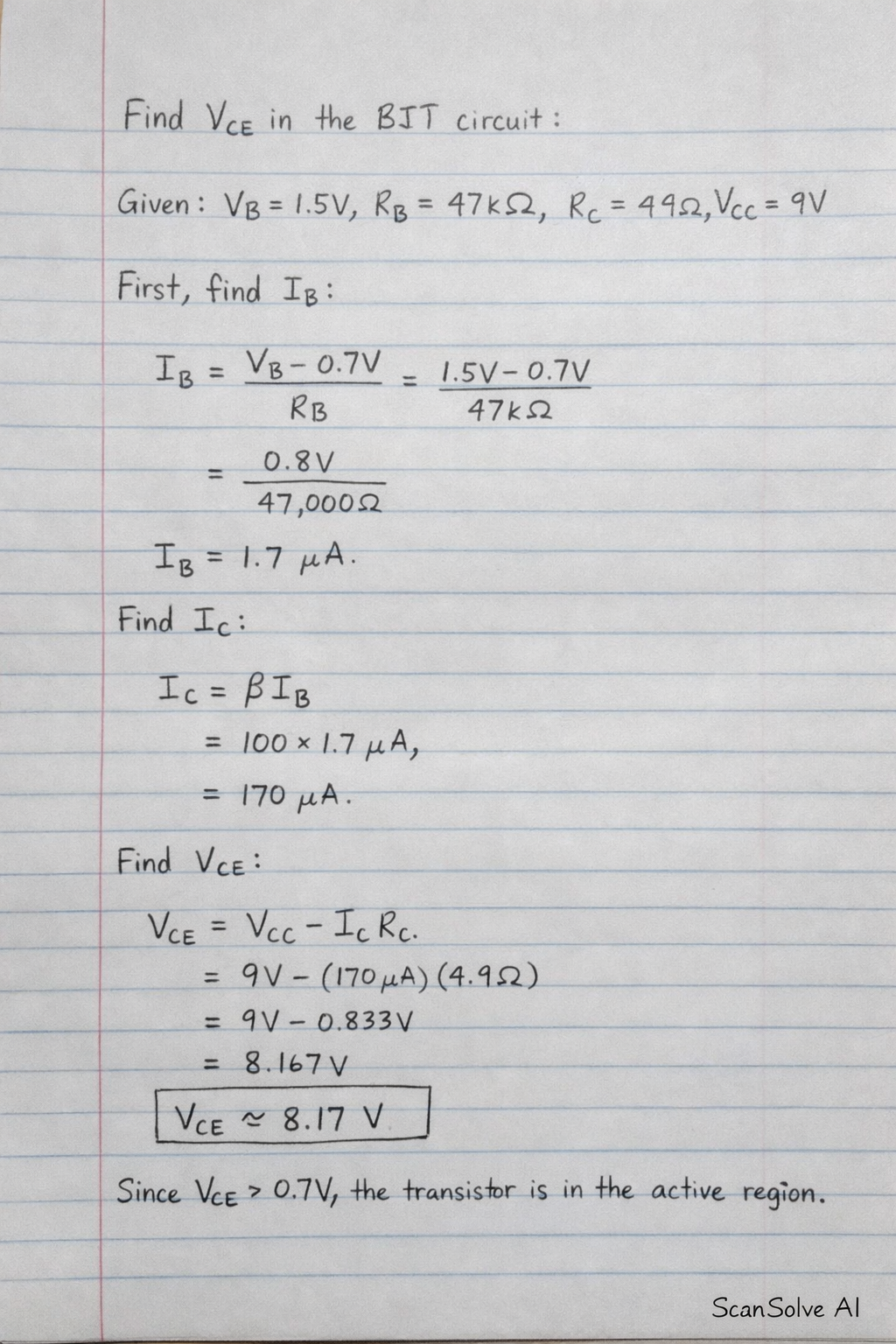
Please calculate the collector-emitter voltage (VCE) for the BJT circuit shown in the image, assuming RC = 4.9 Ohms and VCC = 9V. The base voltage (VB) is also provided in the image.
Computer Science
ScanSolve AI Answer
Here are the calculations for the BJT circuit based on the provided image.
Assumptions:
- The value "4.9V" written near the collector resistor is interpreted as . This assumption is made because using (as in a previous problem context) would lead to a negative , which is not typical for a basic BJT calculation asking for in the active region.
- The "9V" at the top is the collector supply voltage .
Given values from the image:
- Input voltage $V_B =
Was this helpful?
Still stuck on this one?
Ask a follow-up, and the answer starts from this question.
Got a different question?Ask your own question
More Computer Science Questions
QCalculate the base current (IB), collector current (IC), and collector-emitter voltage (V_CE) for a…QFor a BJT circuit with Vcc=12V, Rb=240kΩ, Rc=2.2kΩ, β=100, and Vbe=0.7V, calculate Ib, Ic, Vce, and…QFind RC and RB for the transistor circuit shown in Fig. 4.123, given VCC = 12V, IC = 2mA, VC = 7.6V…QFor a transistor circuit, given Vcc, Ic, Vc, Ve, and beta, calculate Rc, Re, and Rb.QFor the common-base configuration of Fig. 5.165, determine re given RB = 6.8 k RC = 4.7 k alpha…
Handwritten Step-by-Step Solution
Get this as a handwritten image on WhatsApp — like a tutor wrote it for you.
Try on WhatsApp