
We read your photo as:
For a BJT circuit with Vcc=12V, Rb=240kΩ, Rc=2.2kΩ, β=100, and Vbe=0.7V, calculate Ib, Ic, Vce, and confirm the operating region.
ScanSolve AI Answer
Answers
2 partsStep-by-step solution
5 stepsHere are the calculations for the BJT circuit:
Part a· 3 steps
Find , ,
Calculate the base current .
The formula for the base current in a fixed-bias configuration is:
Substitute the given values:
Calculate the collector current .
The formula for the collector current is:
Substitute the values:
Calculate the collector-emitter voltage .
The formula for the collector-emitter voltage is:
Substitute the values:
The calculated values are:
Part b
Confirm the operating region
To confirm the operating region, we compare with (typically ) and check if is less than the saturation current .
First, calculate the maximum possible collector current (saturation current) if the transistor were in saturation:
Assuming :
Now, compare the calculated and :
- Our calculated is less than .
- Our calculated is greater than .
Since (forward-biased base-emitter junction) and , the transistor is operating in the active region.
Part c101
Calculate the stability factor and comment on its significance.
Calculate the stability factor .
For a fixed-bias configuration, the stability factor (with respect to ) is given by:
Substitute the given :
Comment on its significance.
The stability factor indicates how much the collector current changes due to variations in the reverse saturation current (which is highly temperature-dependent). A high value of (like 101) means that the collector current is very sensitive to changes in . This implies that the operating point of the fixed-bias circuit is unstable with respect to temperature variations, making it prone to thermal runaway.
Try one yourself
A new problem that tests the same skill.
Still stuck on this one?
Ask a follow-up, and the answer starts from this question.
More Computer Science Questions
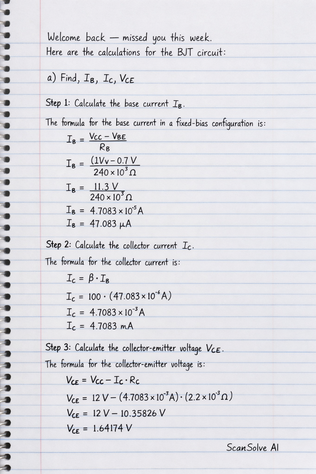
Handwritten Step-by-Step Solution
Get this as a handwritten image on WhatsApp — like a tutor wrote it for you.
Try on WhatsApp