This computer science problem involves algorithmic thinking and programming concepts. The solution below explains the approach, logic, and implementation step by step.
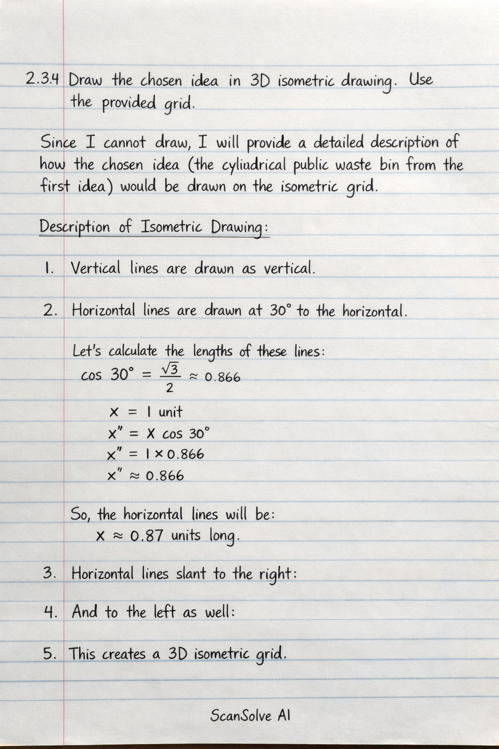
Draw the chosen idea in 3D isometric drawing. Use the provided grid.
Computer Science

ScanSolve AI Answer
7 steps2.3.4 Draw the chosen idea in 3D isometric drawing. Use the provided grid.
Since I cannot draw, I will provide a detailed description of how the chosen idea (the cylindrical public waste bin from the first idea) would be drawn on the isometric grid.
Description of Isometric Drawing:
The drawing would be constructed on the provided isometric grid, where vertical lines are drawn vertically, and horizontal lines are drawn at 30-degree angles to the horizontal.
- Base: A circular base would be represented as an isometric ellipse on the grid, positioned at the bottom. The thickness of the base would be shown by drawing a parallel ellipse slightly below and connecting the edges with vertical lines.
- Bin Body: Rising vertically from the base, the main cylindrical body of the bin would be drawn. The top and bottom of the cylinder would be represented by isometric ellipses. The body would be slightly tapered, meaning the top ellipse would be slightly larger than the bottom one, creating a subtle conical shape.
- Domed Lid: On top of the bin body, a domed lid would be drawn. This would involve drawing another isometric ellipse for the base of the dome, and then sketching a curved, dome-like shape rising from it.
- Waste Opening: A wide, angled rectangular opening for waste insertion would be cut into the domed lid. This would be drawn as an isometric rectangle, angled downwards into the dome.
- Access Door (Hidden Detail): On the side of the bin body, a rectangular access door would be indicated with dashed lines. This door would be shown as a hinged panel, with dashed lines representing the hinge mechanism on one vertical edge and a locking latch on the opposite vertical edge.
- Inner Liner (Hidden Detail): Inside the main bin body, a removable inner liner (a cylindrical container) would be shown with dashed lines, indicating its position and shape within the outer shell.
- Mounting Bolts (Hidden Detail): Dashed lines would indicate the positions of mounting bolts through the base plate, showing how the bin would be secured to the ground.
Labels on the Drawing:
- "Domed Lid" (pointing to the top cover)
- "Waste Opening" (pointing to the slot on the lid)
- "Bin Body" (pointing to the main cylindrical section)
- "Base Plate" (pointing to the bottom support)
- "Access Door" (pointing to the dashed outline of the door on the side)
- "Inner Liner" (pointing to the dashed outline of the container inside)
- "Locking Latch" (pointing to the dashed detail on the access door)
Was this helpful?
Still stuck on this one?
Ask a follow-up, and the answer starts from this question.
Got a different question?Ask your own question
More Computer Science Questions
QDraw the isometric from the given views.QThe figure below is drawn in third angle orthographic projection. Draw the isometric view.QIn the space below make a neat orthographic drawing to a scale 2:1 of the given isometric view.QDraw the orthographic views of the given isometric figure using first-angle and third-angle projecti…QProduce freehand pictorial sketches (oblique and isometric) of a fixed body with specific dimensions…

Handwritten Step-by-Step Solution
Get this as a handwritten image on WhatsApp — like a tutor wrote it for you.
Try on WhatsAppScanSolve AI Answer
2.3.4 Draw the chosen idea in 3D isometric drawing. Use the provided grid. Since I cannot draw, I will provide a detailed description of how the chosen idea (the cylindrical public waste bin from the first idea) would be drawn on the isometric grid. Description of Isometric Drawing: The drawing would be constructed on the provided isometric grid, where vertical lines are drawn vertically, and horizontal lines are drawn at 30-degree angles to the horizontal. 1. Base: A circular base would be represented as an isometric ellipse on the grid, positioned at the bottom. The thickness of the base would be shown by drawing a parallel ellipse slightly below and connecting the edges with vertical lines. 2. Bin Body: Rising vertically from the base, the main cylindrical body of the bin would be drawn. The top and bottom of the cylinder would be represented by isometric ellipses. The body would be slightly tapered, meaning the top ellipse would be slightly larger than the bottom one, creating a subtle conical shape. 3. Domed Lid: On top of the bin body, a domed lid would be drawn. This would involve drawing another isometric ellipse for the base of the dome, and then sketching a curved, dome-like shape rising from it. 4. Waste Opening: A wide, angled rectangular opening for waste insertion would be cut into the domed lid. This would be drawn as an isometric rectangle, angled downwards into the dome. 5. Access Door (Hidden Detail): On the side of the bin body, a rectangular access door would be indicated with dashed lines. This door would be shown as a hinged panel, with dashed lines representing the hinge mechanism on one vertical edge and a locking latch on the opposite vertical edge. 6. Inner Liner (Hidden Detail): Inside the main bin body, a removable inner liner (a cylindrical container) would be shown with dashed lines, indicating its position and shape within the outer shell. 7. Mounting Bolts (Hidden Detail): Dashed lines would indicate the positions of mounting bolts through the base plate, showing how the bin would be secured to the ground. Labels on the Drawing: "Domed Lid" (pointing to the top cover) "Waste Opening" (pointing to the slot on the lid) "Bin Body" (pointing to the main cylindrical section) "Base Plate" (pointing to the bottom support) "Access Door" (pointing to the dashed outline of the door on the side) "Inner Liner" (pointing to the dashed outline of the container inside) "Locking Latch" (pointing to the dashed detail on the access door)