
We read your photo as:
FIGURE 2, DIAGRAM SHEET 2 (attached), shows two views of a machine part in third angle orthographic projection, draw the following views of the machine part: To scale 1:1 and in third angle orthographic projection.
ScanSolve AI Answer
The provided image contains only the text of Question 3. FIGURE 2, DIAGRAM SHEET 2, which shows the machine part, is not included. Therefore, I cannot complete parts 3.1, 3.2, and 3.3 as they require the actual drawing. I can, however, provide the information for parts 3.4 and 3.5.
- 3.1 The given top view
- Cannot be drawn without FIGURE 2.
- 3.2 A full-sectional front view on cutting plane R-R
- Cannot be drawn without FIGURE 2.
- 3.3 A removed sectional view on cutting plane A-A
- Cannot be drawn without FIGURE 2.
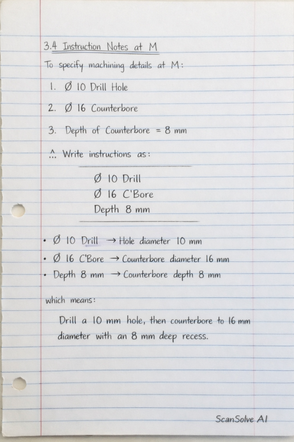
3.4 At M, provide the necessary instruction notes to indicate that a hole must be drilled in the work piece and that a hole must be counter bored.
The instruction notes would typically be placed near the feature 'M' on the drawing.
- For the drilled hole:
- For the counterbored hole: Alternatively, a combined note for a counterbored hole might specify the through-hole diameter first, then the counterbore diameter and depth. However, based on the phrasing, separate notes for the two distinct operations are implied.
3.5 Print a title and scale centrally beneath the layout.
Assuming a generic title for the machine part and using the specified scale:
- Title: MACHINE PART
- Scale: 1:1
These would be placed in the title block area, centrally beneath the drawing layout.
Still stuck on this one?
Ask a follow-up, and the answer starts from this question.
More Computer Science Questions
Handwritten Step-by-Step Solution
Get this as a handwritten image on WhatsApp — like a tutor wrote it for you.
Try on WhatsApp