

This mathematics problem involves applying core mathematical principles and formulas. Below you will find a complete step-by-step solution with detailed explanations for each step, helping you understand not just the answer but the method behind it.
ScanSolve AI Answer
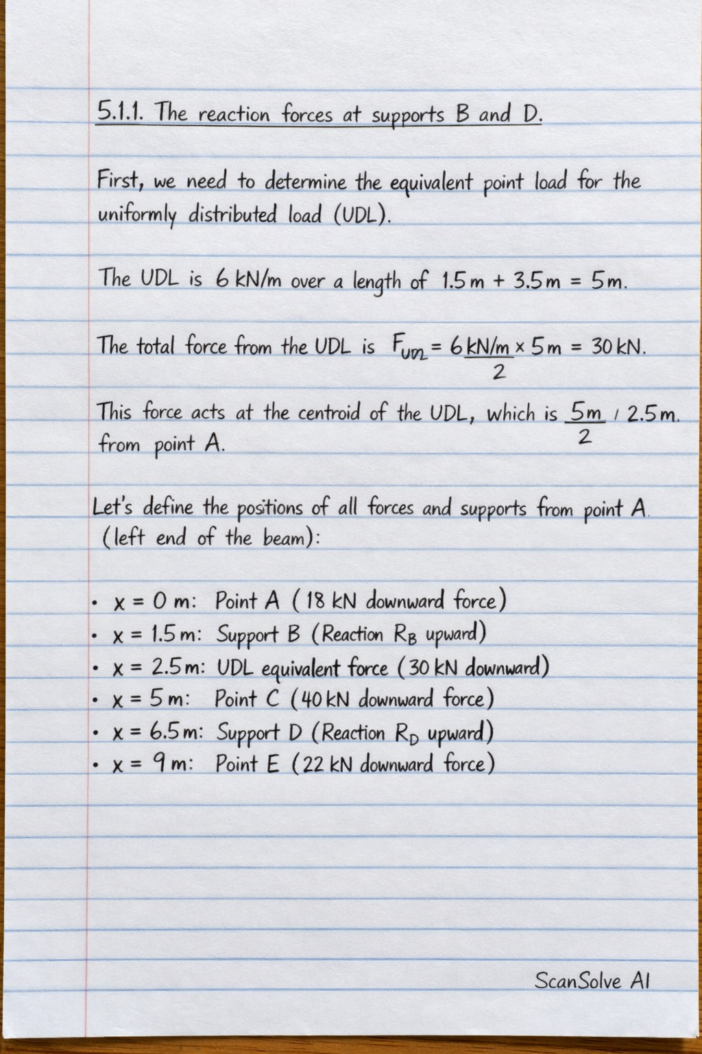
Here's a step-by-step solution for the given problems. 5.1.1 The reaction forces at supports B and D. First, we need to determine the equivalent point load for the uniformly distributed load (UDL). The UDL is 6 kN/m over a length of 1.5 m + 3.5 m = 5 m. The total force from the UDL is F_UDL = 6 kN/m × 5 m = 30 kN. This force acts at the centroid of the UDL, which is 5 m / 2 = 2.5 m from point A. Let's define the positions of all forces and supports from point A (left end of the beam): Point A: x = 0 m (18 kN downward force) Support B: x = 1.5 m (Reaction R_B upward) UDL equivalent force: x = 2.5 m (30 kN downward force) Point C: x = 1.5 m + 3.5 m = 5 m (40 kN downward force) Support D: x = 5 m + 1.5 m = 6.5 m (Reaction R_D upward) Point E: x = 6.5 m + 2.5 m = 9 m (22 kN downward force) Step 1: Apply the equilibrium equation for the sum of vertical forces. Assume upward forces are positive. F_y = 0 R_B + R_D - 18 kN - 30 kN - 40 kN - 22 kN = 0 R_B + R_D - 110 kN = 0 R_B + R_D = 110 kN (1) Step 2: Apply the equilibrium equation for the sum of moments about support B. Assume clockwise moments are positive. M_B = 0 The moment arms are calculated relative to point B (x=1.5 m). (18 kN × 1.5 m) + (30 kN × (2.5 m - 1.5 m)) + (40 kN × (5 m - 1.5 m)) - (R_D × (6.5 m - 1.5 m)) + (22 kN × (9 m - 1.5 m)) = 0 (18 × 1.5) + (30 × 1) + (40 × 3.5) - (R_D × 5) + (22 × 7.5) = 0 27 + 30 + 140 - 5R_D + 165 = 0 362 - 5R_D = 0 5R_D = 362 R_D = (362)/(5) = 72.4 kN Step 3: Substitute the value of R_D into Equation (1) to find R_B. R_B + 72.4 kN = 110 kN R_B = 110 kN - 72.4 kN R_B = 37.6 kN The reaction forces are: R_B = 37.6 kN R_D = 72.4 kN 5.1.2 Draw the shear force diagram for the beam. We will calculate the shear force at key points along the beam, starting from the left (point A). At A (x=0 m): V_A = -18 kN (downward force) Just before B (x=1.5^- m): The UDL acts from x=0 to x=5 m. Shear force due to UDL up to B = 6 kN/m × 1.5 m = 9 kN. V_B^- = -18 kN - 9 kN = -27 kN Just after B (x=1.5^+ m): V_B^+ = V_B^- + R_B = -27 kN + 37.6 kN = 10.6 kN Just before C (x=5^- m): Shear force from B to C due to UDL = 6 kN/m × (5 m - 1.5 m) = 6 kN/m × 3.5 m = 21 kN. V_C^- = V_B^+ - 21 kN = 10.6 kN - 21 kN = -10.4 kN Just after C (x=5^+ m): V_C^+ = V_C^- - 40 kN = -10.4 kN - 40 kN = -50.4 kN Just before D (x=6.5^- m): There are no distributed loads or point loads between C and D. V_D^- = V_C^+ = -50.4 kN Just after D (x=6.5^+ m): V_D^+ = V_D^- + R_D = -50.4 kN + 72.4 kN = 22 kN At E (x=9 m): There are no distributed loads or point loads between D and E. V_E = V_D^+ - 22 kN = 22 kN - 22 kN = 0 kN (This confirms the calculations are correct as the shear force closes to zero at the end of the beam). The shear force diagram will be drawn based on these values. From A to B, the shear force decreases linearly from -18 kN to -27 kN. At B, it jumps up to 10.6 kN. From B to C, it decreases linearly from 10.6 kN to -10.4 kN. At C, it jumps down to -50.4 kN. From C to D, it remains constant at -50.4 kN. At D, it jumps up to 22 kN. From D to E, it remains constant at 22 kN and then drops to 0 kN at E. The point where the shear force is zero between B and C can be found by similar triangles or by setting the shear force equation to zero. Let x' be the distance from B where shear force is zero. 10.6 - 6x' = 0 x' = (10.6)/(6) ≈ 1.767 m from B. This corresponds to x = 1.5 + 1.767 = 3.267 m from A. The shear force diagram is as follows: [scale=0.8] % Beam line (0,0) -- (9,0); % Supports (1.5,-0.5) -- (1.5,0.5); (1.5,-0.5) -- (1.2,-0.8); (1.5,-0.5) -- (1.8,-0.8); (6.5,-0.5) -- (6.5,0.5); (6.5,-0.5) -- (6.2,-0.8); (6.5,-0.5) -- (6.8,-0.8); % Labels for points at (0,-0.3) A; at (1.5,-0.3) B; at (5,-0.3) C; at (6.5,-0.3) D; at (9,-0.3) E; % Shear force diagram [blue, thick] (0,0) node[left] V -- (0,-1.8) node[below left] -18; [blue, thick] (0,-1.8) -- (1.5,-2.7) node[below left] -27; [blue, thick] (1.5,-2.7) -- (1.5,1.06) node[above left] 10.6; [blue, thick] (1.5,1.06) -- (3.267,0); % Zero point [blue, thick] (3.267,0) -- (5,-1.04) node[below left] -10.4; [blue, thick] (5,-1.04) -- (5,-5.04) node[below left] -50.4; [blue, thick] (5,-5.04) -- (6.5,-5.04); [blue, thick] (6.5,-5.04) -- (6.5,2.2) node[above left] 22; [blue, thick] (6.5,2.2) -- (9,2.2) -- (9,0); % X-axis for diagram [dashed] (0,0) -- (9,0); % Y-axis for diagram [dashed] (0,-6) -- (0,3); 5.2 Calculate the coordinates of the centroid of the lamina shown in FIGURE 2. We will divide the lamina into simpler geometric shapes and use the principle of composite areas. Let's divide the shape into three rectangles: Rectangle 1 (Vertical part on left): Width = 40 mm Height = 80 mm Area A_1 = 40 × 80 = 3200 mm^2 Centroid x_1 = (40)/(2) = 20 mm Centroid y_1 = (80)/(2) = 40 mm Rectangle 2 (Horizontal part on right): Width = 100 mm - 40 mm = 60 mm Height = 40 mm Area A_2 = 60 × 40 = 2400 mm^2 Centroid x_2 = 40 mm + (60)/(2) = 40 + 30 = 70 mm Centroid y_2 = (40)/(2) = 20 mm Rectangle 3 (Hole): This is a cutout, so its area will be negative. Width = 20 mm Height = 20 mm Area A_3 = -(20 × 20) = -400 mm^2 Centroid x_3 = 20 mm + (20)/(2) = 20 + 10 = 30 mm Centroid y_3 = 20 mm + (20)/(2) = 20 + 10 = 30 mm Step 1: Calculate the total area A_total. A_total = A_1 + A_2 + A_3 A_total = 3200 mm^2 + 2400 mm^2 - 400 mm^2 A_total = 5200 mm^2 Step 2: Calculate the x-coordinate of the centroid (x). x = (A_1 x_1 + A_2 x_2 + A_3 x_3)/(A_total) x = ((3200 × 20) + (2400 × 70) + (-400 × 30))/(5200) x = (64000 + 168000 - 12000)/(5200) x = (220000)/(5200) x = (2200)/(52) = (550)/(13) ≈ 42.31 mm Step 3: Calculate the y-coordinate of the centroid (y). y = (A_1 y_1 + A_2 y_2 + A_3 y_3)/(A_total) y = ((3200 × 40) + (2400 × 20) + (-400 × 30))/(5200) y = (128000 + 48000 - 12000)/(5200) y = (164000)/(5200) y = (1640)/(52) = (410)/(13) ≈ 31.54 mm The coordinates of the centroid are: (x, y) = (42.31 mm, 31.54 mm) What's next? Send 'em! 📸