a. A.d.c. circuit comprises three closed loops. Applying Kirchhoff's laws to the closed loops gives the following equations for current flow in milliamperes: 2I 1 + 31 41, = 26 -71, + 21, + 61, = 12 Use determinants to solve for I₁, 1₂ and 13
|Physics
a. A.d.c. circuit comprises three closed loops. Applying Kirchhoff's laws to the closed loops gives the following equations for current flow in milliamperes: 2I 1 + 31 41, = 26 -71, + 21, + 61, = 12 Use determinants to solve for I₁, 1₂ and 13
ScanSolve AI Answer
Answer
17.40sin(100πt+0.694) V
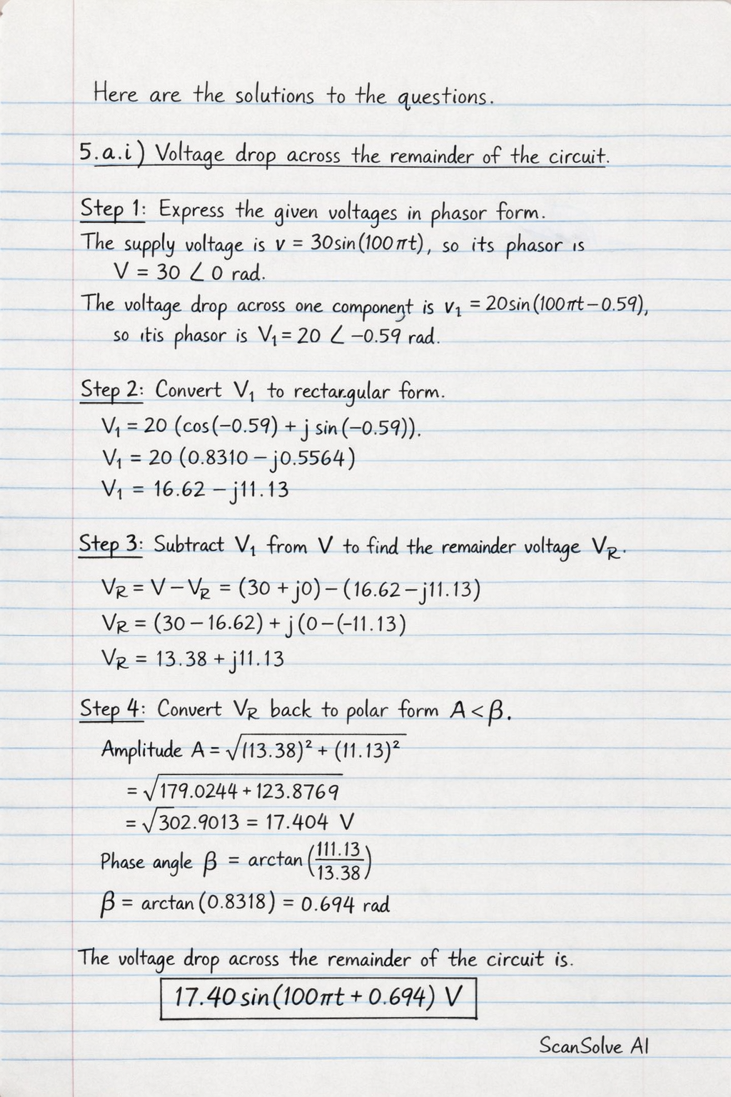
Here are the solutions to the questions.
5.a.i) Voltage drop across the remainder of the circuit
Step 1: Express the given voltages in phasor form.
The supply voltage is v=30sin(100πt), so its phasor is V=30∠0 rad.
The voltage drop across one component is v1=20sin(100πt−0.59), so its phasor is V1=20∠−0.59 rad.
Step 2: Convert V1 to rectangular form.
V1=20(cos(−0.59)+jsin(−0.59))V1≈20(0.8310−j0.5564)V1≈16.62−j11.13
Step 3: Subtract V1 from V to find the remainder voltage VR.
VR=V−V1=(30+j0)−(16.62−j11.13)VR=(30−16.62)+j(0−(−11.13))VR=13.38+j11.13
Step 4: Convert VR back to polar form A∠β.
Amplitude A=(13.38)2+(11.13)2=179.0244+123.8769=302.9013≈17.404 V.
Phase angle β=arctan(13.3811.13)=arctan(0.8318)≈0.694 rad.
The voltage drop across the remainder of the circuit is \boxed{*17.40\sin(100\pi t + 0.694) V*}.
5.a.ii) Supply frequency
Step 1: Identify the angular frequency ω from the supply voltage equation v=30sin(100πt).
ω=100π rad/s.
Step 2: Use the relationship ω=2πf to find the frequency f.
100π=2πff=2π100π=50 Hz.
The supply frequency is ∗50Hz∗.
5.a.iii) Periodic time of the supply
Step 1: Use the relationship between periodic time T and frequency f.
T=f1.
Step 2: Substitute the frequency found in part (ii).
T=501=0.02 s.
The periodic time of the supply is ∗0.02s∗.
5.a.iv) r.m.s. value of the supply voltage
Step 1: Identify the peak voltage Vm from the supply voltage equation v=30sin(100πt).
Vm=30 V.
Step 2: Use the formula for the RMS value of a sinusoidal voltage.
Vrms=2Vm.
Vrms=230=2302=152 V.
Vrms≈15×1.4142=21.213 V.
The r.m.s. value of the supply voltage is \boxed{\text{*15\sqrt{2} V (or approx. 21.21 V)*}}.
5.b) Solve for I1,I2,I3 using determinants
Step 1: Write the system of equations in matrix form AX=B.
21−73−52−4−36I1I2I3=26−8712
Step 2: Calculate the determinant of the coefficient matrix D.
Step 1: Draw free-body diagrams and set up equations of motion.
Assume mA moves down, mB moves right, and mC moves up. Let a be the acceleration.
For mass A: mAg−T1=mAa4(10)−T1=4a⇒40−T1=4a (Eq. 1)
For mass C: T2−mCg=mCaT2−1(10)=1a⇒T2−10=a (Eq. 2)
For mass B:
Normal force N=mBg=3(10)=30 N.
Friction force fk=μN=0.6×30=18 N.
The equation of motion for B (moving right): T1−T2−fk=mBaT1−T2−18=3a (Eq. 3)
Step 2: Solve the system of equations.
From (Eq. 1): T1=40−4a
From (Eq. 2): T2=10+a
Substitute T1 and T2 into (Eq. 3):
(40−4a)−(10+a)−18=3a40−4a−10−a−18=3a12−5a=3a12=8aa=812=1.5m/s2
Step 3: Calculate the tensions T1 and T2.
T1=40−4a=40−4(1.5)=40−6=34 NT2=10+a=10+1.5=11.5 N
The acceleration of the masses is \boxed{*1.5 \text{ m/s^2}*}.
The tension in the string between A and B is \boxed{\text{*34 \text{ N}}*}.
The tension in the string between B and C is \boxed{\text{*11.5 \text{ N}}*}.
5.d) Atwood machine
Given: m1=4 kg, m2=3 kg, g=9.81m/s2. Released from rest.
Step 1: Set up equations of motion for each mass.
Let T be the tension in the string and a be the acceleration.
For m1 (moving downwards): m1g−T=m1a4(9.81)−T=4a⇒39.24−T=4a (Eq. 1)
For m2 (moving upwards): T−m2g=m2aT−3(9.81)=3a⇒T−29.43=3a (Eq. 2)
Step 2: Solve for acceleration a.
Add (Eq. 1) and (Eq. 2):
(39.24−T)+(T−29.43)=4a+3a9.81=7aa=79.81≈1.4014m/s2
i) The acceleration of each mass is \boxed{*1.4014 \text{ m/s^2}*}. (4 kg mass downwards, 3 kg mass upwards).
Step 3: Calculate the speed after 2 seconds.
Using the kinematic equation v=u+at, with initial velocity u=0.
v=0+(1.4014)(2)v=2.8028 m/s
ii) Their speed after 2 seconds is \boxed{\text{*2.8028 \text{ m/s}}*}.
Step 1: Calculate the necessary sums.
n=10∑x=68∑y=68∑x2=510∑y2=482∑xy=485xˉ=1068=6.8yˉ=1068=6.8
i)Scatter diagram for the data:
A scatter diagram would plot the given points (x, y) on a Cartesian plane. The x-axis would represent Electrical marks and the y-axis would represent Electronics marks. The points would be: (3,5), (6,6), (4,5), (5,6), (7,7), (8,9), (9,7), (7,8), (10,9), (9,6). Visually, these points would show a general upward trend, indicating a positive correlation between Electrical and Electronics marks.
ii)Equation of best fit and prediction:
To predict the Electrical Installation mark (x) given the Electronics mark (y), we need the regression line of x on y, which has the form x=a+by.
The equation of the regression line of y on x is y=3.5714+0.4748x.
To draw this line on the scatter diagram, you would plot two points from this equation (e.g., for x=3,y≈5.0; for x=10,y≈8.3) and draw a straight line connecting them. This line represents the best linear fit for predicting Electronics marks based on Electrical marks.
3 done, 2 left today. You're making progress.
Was this helpful?
Need help with your own homework?
Get instant step-by-step solutions to any question. Free to start.
Express the given voltages in phasor form. The supply voltage is v = 30(100 t), so its phasor is V = 30 0 rad.
a. A.d.c. circuit comprises three closed loops. Applying Kirchhoff's laws to the closed loops gives the following equations for current flow in milliamperes: 2I 1 + 31 41, = 26 -71, + 21, + 61, = 12 Use determinants to solve for I₁, 1₂ and 13
This physics problem tests your understanding of fundamental physical laws and their applications. The step-by-step solution below breaks down the problem using relevant equations and physical reasoning.
ScanSolve AI Answer
Here are the solutions to the questions. 5.a.i) Voltage drop across the remainder of the circuit Step 1: Express the given voltages in phasor form. The supply voltage is v = 30(100 t), so its phasor is V = 30 0 rad. The voltage drop across one component is v_1 = 20(100 t - 0.59), so its phasor is V_1 = 20 -0.59 rad. Step 2: Convert V_1 to rectangular form. V_1 = 20((-0.59) + j(-0.59)) V_1 ≈ 20(0.8310 - j0.5564) V_1 ≈ 16.62 - j11.13 Step 3: Subtract V_1 from V to find the remainder voltage V_R. V_R = V - V_1 = (30 + j0) - (16.62 - j11.13) V_R = (30 - 16.62) + j(0 - (-11.13)) V_R = 13.38 + j11.13 Step 4: Convert V_R back to polar form A . Amplitude A = sqrt((13.38)^2 + (11.13)^2) = sqrt(179.0244 + 123.8769) = sqrt(302.9013) ≈ 17.404 V. Phase angle = ((11.13)/(13.38)) = (0.8318) ≈ 0.694 rad. The voltage drop across the remainder of the circuit is 17.40(100 t + 0.694) V. 5.a.ii) Supply frequency Step 1: Identify the angular frequency from the supply voltage equation v = 30(100 t). = 100 rad/s. Step 2: Use the relationship = 2 f to find the frequency f. 100 = 2 f f = (100)/(2) = 50 Hz. The supply frequency is 50 Hz. 5.a.iii) Periodic time of the supply Step 1: Use the relationship between periodic time T and frequency f. T = (1)/(f). Step 2: Substitute the frequency found in part (ii). T = (1)/(50) = 0.02 s. The periodic time of the supply is 0.02 s. 5.a.iv) r.m.s. value of the supply voltage Step 1: Identify the peak voltage V_m from the supply voltage equation v = 30(100 t). V_m = 30 V. Step 2: Use the formula for the RMS value of a sinusoidal voltage. V_rms = (V_m)/(sqrt(2)). V_rms = (30)/(sqrt(2)) = 30sqrt(2)2 = 15sqrt(2) V. V_rms ≈ 15 × 1.4142 = 21.213 V. The r.m.s. value of the supply voltage is 15sqrt(2) V (or approx. 21.21 V). 5.b) Solve for I_1, I_2, I_3 using determinants Step 1: Write the system of equations in matrix form AX = B. 2 & 3 & -4 \\ 1 & -5 & -3 \\ -7 & 2 & 6 I_1 \\ I_2 \\ I_3 = 26 \\ -87 \\ 12 Step 2: Calculate the determinant of the coefficient matrix D. D = 2 & 3 & -4 \\ 1 & -5 & -3 \\ -7 & 2 & 6 = 2((-5)(6) - (-3)(2)) - 3((1)(6) - (-3)(-7)) + (-4)((1)(2) - (-5)(-7)) D = 2(-30 + 6) - 3(6 - 21) - 4(2 - 35) D = 2(-24) - 3(-15) - 4(-33) = -48 + 45 + 132 = 129 Step 3: Calculate D_1 by replacing the first column with the constant terms. D_1 = 26 & 3 & -4 \\ -87 & -5 & -3 \\ 12 & 2 & 6 = 26((-5)(6) - (-3)(2)) - 3((-87)(6) - (-3)(12)) + (-4)((-87)(2) - (-5)(12)) D_1 = 26(-30 + 6) - 3(-522 + 36) - 4(-174 + 60) D_1 = 26(-24) - 3(-486) - 4(-114) = -624 + 1458 + 456 = 1290 Step 4: Calculate D_2 by replacing the second column with the constant terms. D_2 = 2 & 26 & -4 \\ 1 & -87 & -3 \\ -7 & 12 & 6 = 2((-87)(6) - (-3)(12)) - 26((1)(6) - (-3)(-7)) + (-4)((1)(12) - (-87)(-7)) D_2 = 2(-522 + 36) - 26(6 - 21) - 4(12 - 609) D_2 = 2(-486) - 26(-15) - 4(-597) = -972 + 390 + 2388 = 1806 Step 5: Calculate D_3 by replacing the third column with the constant terms. D_3 = 2 & 3 & 26 \\ 1 & -5 & -87 \\ -7 & 2 & 12 = 2((-5)(12) - (-87)(2)) - 3((1)(12) - (-87)(-7)) + 26((1)(2) - (-5)(-7)) D_3 = 2(-60 + 174) - 3(12 - 609) + 26(2 - 35) D_3 = 2(114) - 3(-597) + 26(-33) = 228 + 1791 - 858 = 1161 Step 6: Calculate I_1, I_2, I_3 using Cramer's Rule. I_1 = (D_1)/(D) = (1290)/(129) = 10 mA I_2 = (D_2)/(D) = (1806)/(129) = 14 mA I_3 = (D_3)/(D) = (1161)/(129) = 9 mA The currents are I_1 = 10 mA, I_2 = 14 mA, I_3 = 9 mA. 5.c) Acceleration and tensions for three masses Given: m_A = 4 kg, m_B = 3 kg, m_C = 1 kg, = 0.6, g = 10 m/s^2. Step 1: Draw free-body diagrams and set up equations of motion. Assume m_A moves down, m_B moves right, and m_C moves up. Let a be the acceleration. For mass A: m_A g - T_1 = m_A a 4(10) - T_1 = 4a 40 - T_1 = 4a (Eq. 1) For mass C: T_2 - m_C g = m_C a T_2 - 1(10) = 1a T_2 - 10 = a (Eq. 2) For mass B: Normal force N = m_B g = 3(10) = 30 N. Friction force f_k = N = 0.6 × 30 = 18 N. The equation of motion for B (moving right): T_1 - T_2 - f_k = m_B a T_1 - T_2 - 18 = 3a (Eq. 3) Step 2: Solve the system of equations. From (Eq. 1): T_1 = 40 - 4a From (Eq. 2): T_2 = 10 + a Substitute T_1 and T_2 into (Eq. 3): (40 - 4a) - (10 + a) - 18 = 3a 40 - 4a - 10 - a - 18 = 3a 12 - 5a = 3a 12 = 8a a = (12)/(8) = 1.5 m/s^2 Step 3: Calculate the tensions T_1 and T_2. T_1 = 40 - 4a = 40 - 4(1.5) = 40 - 6 = 34 N T_2 = 10 + a = 10 + 1.5 = 11.5 N The acceleration of the masses is 1.5 m/s^2. The tension in the string between A and B is 34 N. The tension in the string between B and C is 11.5 N. 5.d) Atwood machine Given: m_1 = 4 kg, m_2 = 3 kg, g = 9.81 m/s^2. Released from rest. Step 1: Set up equations of motion for each mass. Let T be the tension in the string and a be the acceleration. For m_1 (moving downwards): m_1 g - T = m_1 a 4(9.81) - T = 4a 39.24 - T = 4a (Eq. 1) For m_2 (moving upwards): T - m_2 g = m_2 a T - 3(9.81) = 3a T - 29.43 = 3a (Eq. 2) Step 2: Solve for acceleration a. Add (Eq. 1) and (Eq. 2): (39.24 - T) + (T - 29.43) = 4a + 3a 9.81 = 7a a = (9.81)/(7) ≈ 1.4014 m/s^2 i) The acceleration of each mass is 1.4014 m/s^2. (4 kg mass downwards, 3 kg mass upwards). Step 3: Calculate the speed after 2 seconds. Using the kinematic equation v = u + at, with initial velocity u=0. v = 0 + (1.4014)(2) v = 2.8028 m/s ii) Their speed after 2 seconds is 2.8028 m/s. 5.e) Regression analysis Given data: Electrical (x): 3, 6, 4, 5, 7, 8, 9, 7, 10, 9 Electronics (y): 5, 6, 5, 6, 7, 9, 7, 8, 9, 6 Step 1: Calculate the necessary sums. n = 10 x = 68 y = 68 x^2 = 510 y^2 = 482 xy = 485 x = (68)/(10) = 6.8 y = (68)/(10) = 6.8 i) Scatter diagram for the data: A scatter diagram would plot the given points (x, y) on a Cartesian plane. The x-axis would represent Electrical marks and the y-axis would represent Electronics marks. The points would be: (3,5), (6,6), (4,5), (5,6), (7,7), (8,9), (9,7), (7,8), (10,9), (9,6). Visually, these points would show a general upward trend, indicating a positive correlation between Electrical and Electronics marks. ii) Equation of best fit and prediction: To predict the Electrical Installation mark (x) given the Electronics mark (y), we need the regression line of x on y, which has the form x = a + by. Calculate the slope b: b = (n xy - ( x)( y))/(n y^2 - ( y)^2) b = (10(485) - (68)(68))/(10(482) - (68)^2) = (4850 - 4624)/(4820 - 4624) = (226)/(196) ≈ 1.1531 Calculate the y-intercept a: a = x - by a = 6.8 - (1.1531)(6.8) = 6.8 - 7.8411 = -1.0411 The equation of best fit (x on y) is x = -1.0411 + 1.1531y. Predict the Electrical Installation mark (x) for a student who scored 7 in Electronics (y=7): x = -1.0411 + 1.1531(7) x = -1.0411 + 8.0717 = 7.0306 The predicted Electrical Installation mark is 7.03. iii) Regression line of y on x: The regression line of y on x has the form y = a' + b'x. Calculate the slope b': b' = (n xy - ( x)( y))/(n x^2 - ( x)^2) b' = (10(485) - (68)(68))/(10(510) - (68)^2) = (4850 - 4624)/(5100 - 4624) = (226)/(476) ≈ 0.4748 Calculate the y-intercept a': a' = y - b'x a' = 6.8 - (0.4748)(6.8) = 6.8 - 3.2286 = 3.5714 The equation of the regression line of y on x is y = 3.5714 + 0.4748x. To draw this line on the scatter diagram, you would plot two points from this equation (e.g., for x=3, y ≈ 5.0; for x=10, y ≈ 8.3) and draw a straight line connecting them. This line represents the best linear fit for predicting Electronics marks based on Electrical marks. 3 done, 2 left today. You're making progress.