

This physics problem tests your understanding of fundamental physical laws and their applications. The step-by-step solution below breaks down the problem using relevant equations and physical reasoning.
ScanSolve AI Answer
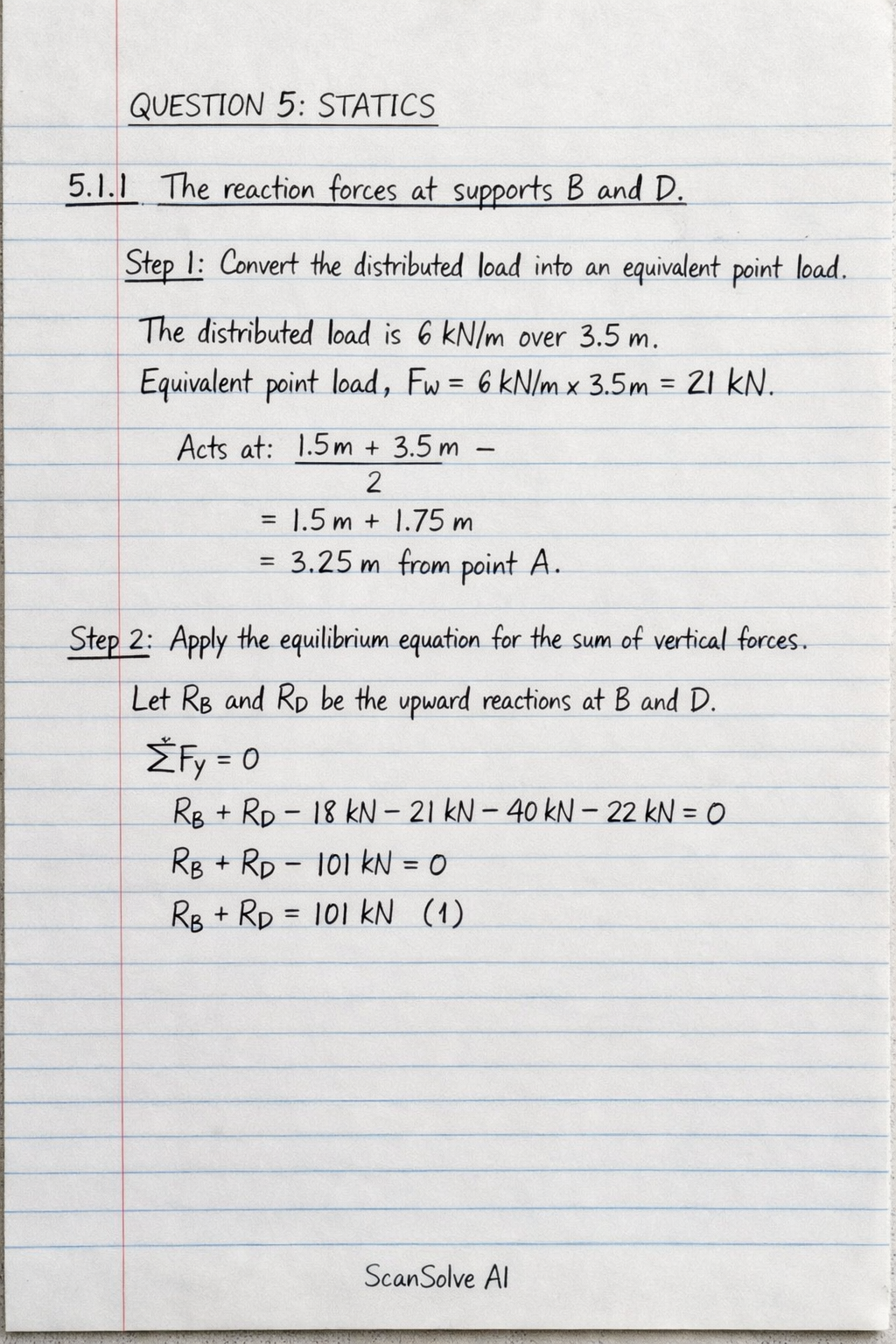
here are the solutions to Question 5. QUESTION 5: STATICS 5.1 A simply supported beam is loaded as shown in FIGURE 1. 5.1.1 The reaction forces at supports B and D. Step 1: Convert the distributed load into an equivalent point load. The distributed load is 6 kN/m over 3.5 m. Equivalent point load F_w = 6 kN/m × 3.5 m = 21 kN. This load acts at the center of the distributed load, which is 1.5 m + 3.5 m2 = 1.5 m + 1.75 m = 3.25 m from point A. Step 2: Apply the equilibrium equation for the sum of vertical forces. Let R_B and R_D be the upward reaction forces at supports B and D, respectively. Upward forces are positive, downward forces are negative. F_y = 0 R_B + R_D - 18 kN - 21 kN - 40 kN - 22 kN = 0 R_B + R_D - 101 kN = 0 R_B + R_D = 101 kN (1) Step 3: Apply the equilibrium equation for the sum of moments about support B. Taking moments about B (clockwise moments are positive): The distance from A to B is 1.5 m. The distance from the equivalent point load F_w to B is 3.25 m - 1.5 m = 1.75 m. The distance from the 40 kN load to B is 5 m - 1.5 m = 3.5 m. The distance from D to B is 6.5 m - 1.5 m = 5 m. The distance from the 22 kN load to B is 9 m - 1.5 m = 7.5 m. M_B = 0 (-18 kN × 1.5 m) + (21 kN × 1.75 m) + (40 kN × 3.5 m) - (R_D × 5 m) + (22 kN × 7.5 m) = 0 -27 + 36.75 + 140 - 5R_D + 165 = 0 314.75 - 5R_D = 0 5R_D = 314.75 R_D = (314.75)/(5) = 62.95 kN Step 4: Calculate R_B using Equation (1). R_B + 62.95 kN = 101 kN R_B = 101 kN - 62.95 kN = 38.05 kN The reaction forces are: R_B = 38.05 kN R_D = 62.95 kN 5.1.2 Draw the shear force diagram for the beam. To draw the shear force diagram, we calculate the shear force at key points along the beam. At A (x = 0 m): Just right of 18 kN load: V_A = -18 kN From A to B (0 m < x < 1.5 m): Shear force is constant: V = -18 kN At B (x = 1.5 m): Just left of R_B: V = -18 kN Just right of R_B: V = -18 kN + 38.05 kN = 20.05 kN From B to 5 m (1.5 m < x < 5 m): Distributed load of 6 kN/m acts downwards. Shear force decreases linearly. Shear force at 5 m (just left of 40 kN load): V_5m, L = 20.05 kN - (6 kN/m × 3.5 m) = 20.05 kN - 21 kN = -0.95 kN The shear force crosses zero at x = 1.5 m + 20.05 kN6 kN/m ≈ 1.5 m + 3.34 m = 4.84 m from A. At 5 m (x = 5 m): Just left of 40 kN load: V = -0.95 kN Just right of 40 kN load: V = -0.95 kN - 40 kN = -40.95 kN From 5 m to D (5 m < x < 6.5 m): Shear force is constant: V = -40.95 kN At D (x = 6.5 m): Just left of R_D: V = -40.95 kN Just right of R_D: V = -40.95 kN + 62.95 kN = 22 kN From D to E (6.5 m < x < 9 m): Shear force is constant: V = 22 kN At E (x = 9 m): Just left of 22 kN load: V = 22 kN Just right of 22 kN load: V = 22 kN - 22 kN = 0 kN Shear Force Diagram Description: Start at -18 kN at point A. Draw a horizontal line from A to B (at x=1.5 m) at -18 kN. At B, draw a vertical line upwards to 20.05 kN. From B to x=5 m, draw a linearly decreasing line from 20.05 kN to -0.95 kN. This line crosses the zero axis at approximately x=4.84 m. At x=5 m, draw a vertical line downwards to -40.95 kN. Draw a horizontal line from x=5 m to D (at x=6.5 m) at -40.95 kN. At D, draw a vertical line upwards to 22 kN. Draw a horizontal line from D to E (at x=9 m) at 22 kN. At E, draw a vertical line downwards to 0 kN. 5.2 Calculate the coordinates of the centroid of the lamina shown in FIGURE 2. Step 1: Divide the lamina into simple geometric shapes and a hole. We can consider the lamina as two rectangles (Rectangle 1 and Rectangle 2) and subtract a rectangular hole (Hole 3). Rectangle 1 (Vertical part): Dimensions: 40 mm × 80 mm Area A_1 = 40 × 80 = 3200 mm^2 Centroid x_1 = (40)/(2) = 20 mm Centroid y_1 = (80)/(2) = 40 mm Rectangle 2 (Horizontal part, to the right of Rectangle 1): Dimensions: (100 - 40) mm × 40 mm = 60 mm × 40 mm Area A_2 = 60 × 40 = 2400 mm^2 Centroid x_2 = 40 + (60)/(2) = 40 + 30 = 70 mm Centroid y_2 = (40)/(2) = 20 mm Hole 3 (Rectangular hole): Dimensions: 20 mm × 20 mm Area A_3 = 20 × 20 = 400 mm^2 (This area will be subtracted) Centroid x_3 = 20 + (20)/(2) = 30 mm Centroid y_3 = 20 + (20)/(2) = 30 mm Step 2: Calculate the total area of the lamina. A_total = A_1 + A_2 - A_3 A_total = 3200 mm^2 + 2400 mm^2 - 400 mm^2 = 5200 mm^2 Step 3: Calculate the x-coordinate of the centroid (x). x = (A_1 x_1 + A_2 x_2 - A_3 x_3)/(A_total) x = (3200 mm^2)(20 mm) + (2400 mm^2)(70 mm) - (400 mm^2)(30 mm)5200 mm^2 x = (64000 + 168000 - 12000)/(5200) mm x = (220000)/(5200) mm = (550)/(13) mm ≈ 42.31 mm Step 4: Calculate the y-coordinate of the centroid (y). y = (A_1 y_1 + A_2 y_2 - A_3 y_3)/(A_total) y = (3200 mm^2)(40 mm) + (2400 mm^2)(20 mm) - (400 mm^2)(30 mm)5200 mm^2 y = (128000 + 48000 - 12000)/(5200) mm y = (164000)/(5200) mm = (410)/(13) mm ≈ 31.54 mm The coordinates of the centroid of the lamina are (42.31 mm, 31.54 mm). Drop the next question.