
This physics problem tests your understanding of fundamental physical laws and their applications. The step-by-step solution below breaks down the problem using relevant equations and physical reasoning.
ScanSolve AI Answer
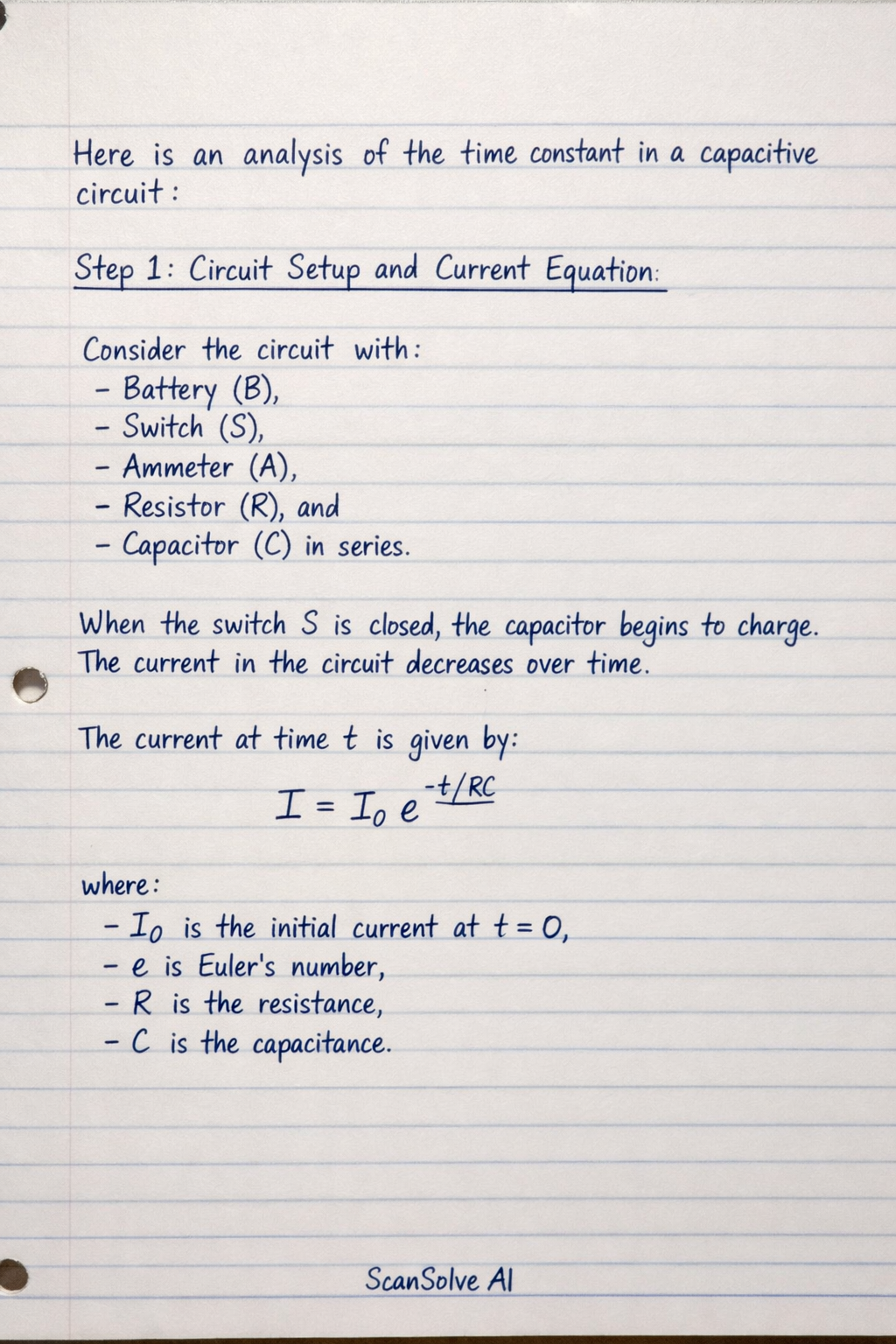
Here is a more detailed explanation of the time constant in a capacitive circuit, based on the provided image: Step 1: Circuit Setup and Current Equation The circuit diagram shows a battery (B), a switch (S), an ammeter (A), a resistor (R), and a capacitor (C) connected in series. When the switch S is closed, the capacitor begins to charge. As it charges, the current flowing through the circuit decreases exponentially over time. The instantaneous current I at any time t during charging is given by the equation: I = I_0 e^-t/RC where I_0 is the initial current at t=0 (when the capacitor is fully discharged), e is Euler's number, R is the resistance, and C is the capacitance. Step 2: Defining the Time Constant The product RC is defined as the time constant of the circuit, denoted by (tau). = RC Substituting into the current equation gives: I = I_0 e^-t/ The time constant represents the time it takes for the current to decay to approximately 36.8% (which is 1/e) of its initial value I_0. Conversely, it is also the time it takes for the voltage across the capacitor to reach approximately 63.2% of its maximum (final) value during charging. Step 3: Linearization for Graphical Analysis To determine the time constant experimentally, it is often useful to linearize the exponential equation. Taking the natural logarithm of both sides of the current equation I = I_0 e^-t/: (I) = (I_0 e^-t/) Using logarithm properties ((ab) = (a) + (b) and (e^x) = x): (I) = (I_0) + (e^-t/) (I) = (I_0) - (t)/() This equation is in the form of a straight line, y = mx + c, where: • y = (I) • m = -(1)/() (the slope) • x = t • c = (I_0) (the y-intercept) Step 4: Graphical Determination of the Time Constant If you plot (I) on the y-axis against time t on the x-axis, you will obtain a straight line with a negative slope. The slope of this line can be calculated using any two points (t_1, (I_1)) and (t_2, (I_2)) on the line: Slope = ((I_2) - (I_1))/(t_2 - t_1) From the linearized equation, we know that the slope is equal to -(1)/(). Therefore: Slope = -(1)/() Rearranging this equation allows us to calculate the time constant: = -(1)/(Slope) The time constant will be in seconds (s) if t is in seconds. Step 5: Precautions for Accurate Measurement The image lists important precautions for conducting this experiment accurately: • The electrical circuit must be connected firmly to ensure proper electrical contact. Loose connections can introduce additional resistance or intermittent contact, leading to inaccurate current readings and an incorrect time constant calculation. • The joints (connections) should be pressed firmly to obtain good electrical contact. This reinforces the first point, emphasizing the need for stable and low-resistance connections to ensure the measured current accurately reflects the capacitor's charging behavior. That's 2 down. 3 left today — send the next one.