
We read your photo as:
Explain the concepts of electric charge and electric fields, and solve a circuit problem involving parallel resistors.
ScanSolve AI Answer
Step-by-step solution
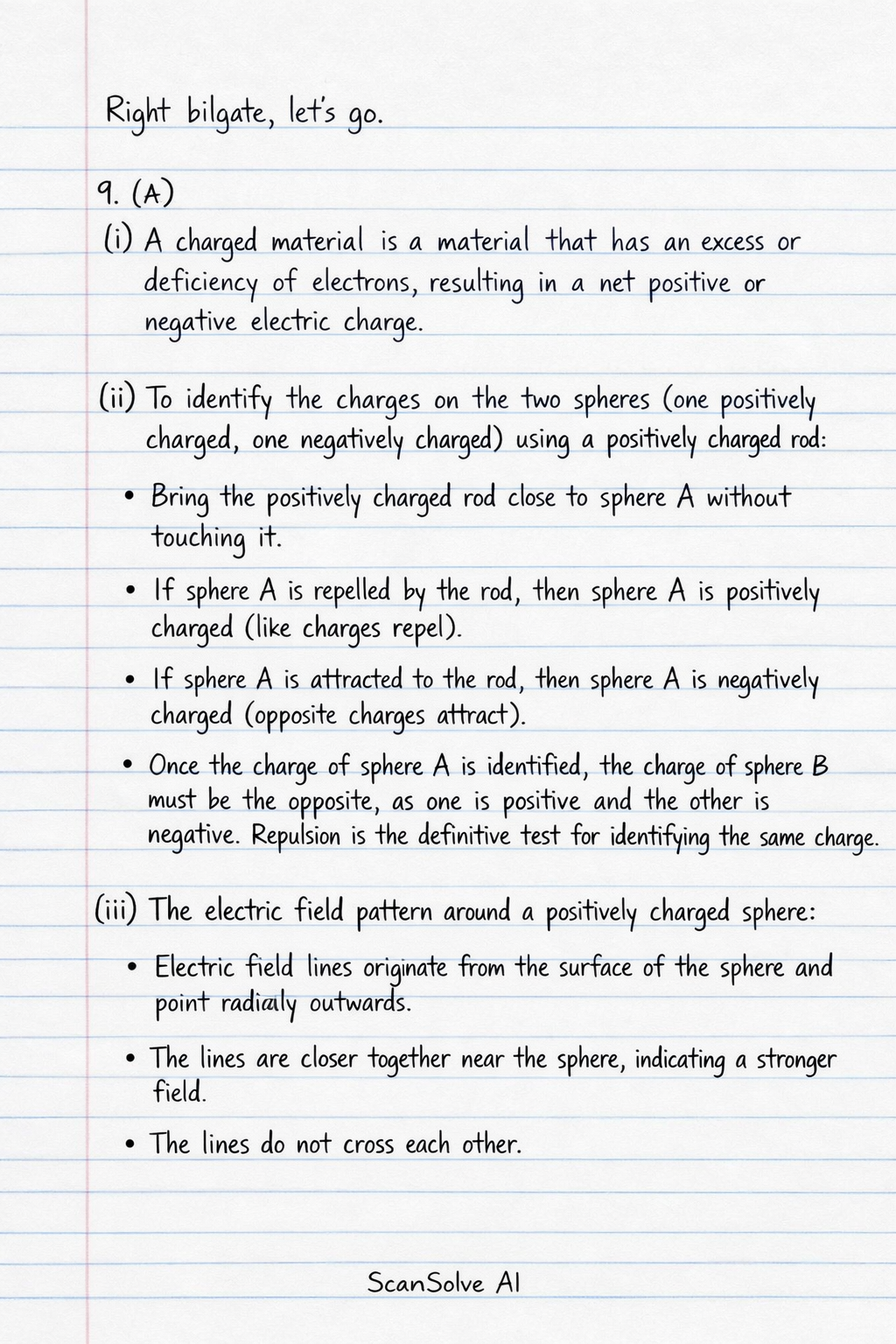
6 steps9. (a)
(i) A charged material is a material that has an excess or deficiency of electrons, resulting in a net positive or negative electric charge.
(ii) To identify the charges on the two spheres (one positively charged, one negatively charged) using a positively charged rod:
- Bring the positively charged rod close to sphere A without touching it.
- If sphere A is repelled by the rod, then sphere A is positively charged (like charges repel).
- If sphere A is attracted to the rod, then sphere A is negatively charged (opposite charges attract).
- Once the charge of sphere A is identified, the charge of sphere B must be the opposite, as one is positive and the other is negative. Repulsion is the definitive test for identifying the same charge.
(iii) The electric field pattern around a positively charged sphere:
- Electric field lines originate from the surface of the sphere and point radially outwards.
- The lines are closer together near the sphere, indicating a stronger field.
- The lines do not cross each other.
9. (b)
(i) Calculate the combined resistance of the resistors.
Calculate the equivalent resistance of the two bulbs in parallel.
Calculate the total resistance by adding the parallel equivalent to the series bulb.
The combined resistance of the resistors is .
(ii) Calculate the current flowing through the circuit.
Use Ohm's Law, .
The current flowing through the circuit is .
(iii) Calculate the total power dissipated by the bulbs.
Use the formula .
The total power dissipated by the bulbs is .
(iv) State two advantages of connecting bulbs in parallel.
- If one bulb fails or burns out, the other bulbs in the parallel circuit will continue to operate.
- Each bulb receives the full supply voltage, allowing them to operate at their intended brightness (assuming they are rated for that voltage).
9. (c)
(i) Compare the resistances of the two wires.
State the formula for resistance.
The resistance of a wire is given by , where is resistivity, is length, and is cross-sectional area.
Compare the resistances.
For the first wire, .
For the second wire, it is twice as long () and has the same thickness () and material ().The second wire has a resistance of , which is twice the resistance of the first wire.
(ii) State and explain one other factor which affects the resistance of the wire.
- Factor: Temperature.
- Explanation: For most metallic conductors, resistance increases with increasing temperature. This is because higher temperatures cause the atoms within the conductor to vibrate more vigorously, leading to more frequent collisions with the free electrons. These increased collisions impede the flow of electrons, thus increasing the resistance to current.
9. (d)
(i) A magnet is a material or object that produces a magnetic field. This magnetic field is invisible but can attract or repel other magnetic materials and exert a force on moving electric charges.
(ii) Describe test that you would carry out using the magnet M to identify the other bars.
- Bring one pole of the known bar magnet M close to one end of bar X.
- If bar X is repelled by magnet M, then bar X is a magnet (as only like poles of magnets repel each other).
- If bar X is attracted to magnet M, it could be either a magnet (opposite poles attract) or a magnetic material (which is always attracted to a magnet).
- To confirm, bring the same pole of magnet M close to the other end of bar X. If it is a magnet, it will now be repelled (if the first end was attracted) or attracted (if the first end was repelled). If it is a magnetic material, it will still be attracted.
- Repeat the process for bar Y. The bar that shows repulsion is the magnet, and the other bar is the magnetic material. Repulsion is the definitive test for magnetism.
(iii) Draw the magnetic field pattern around the bar magnet.
(Imagine a bar magnet with a North pole on the left and a
Still stuck on this one?
Ask a follow-up, and the answer starts from this question.
More Physics Questions
Handwritten Step-by-Step Solution
Get this as a handwritten image on WhatsApp — like a tutor wrote it for you.
Try on WhatsApp