Consider the loaded beam in FIGURE 1 below and answer the following questions. Calculate the reactions at the supports. Calculate bending moments at B, C and D. Draw the SF and the BM diagrams. Also, determine the magnitude of the maximum bending moment and its position.

Physics
Consider the loaded beam in FIGURE 1 below and answer the following questions. Calculate the reactions at the supports. Calculate bending moments at B, C and D. Draw the SF and the BM diagrams. Also, determine the magnitude of the maximum bending moment and its position.

ScanSolve AI Answer

Answer

68.6 kN

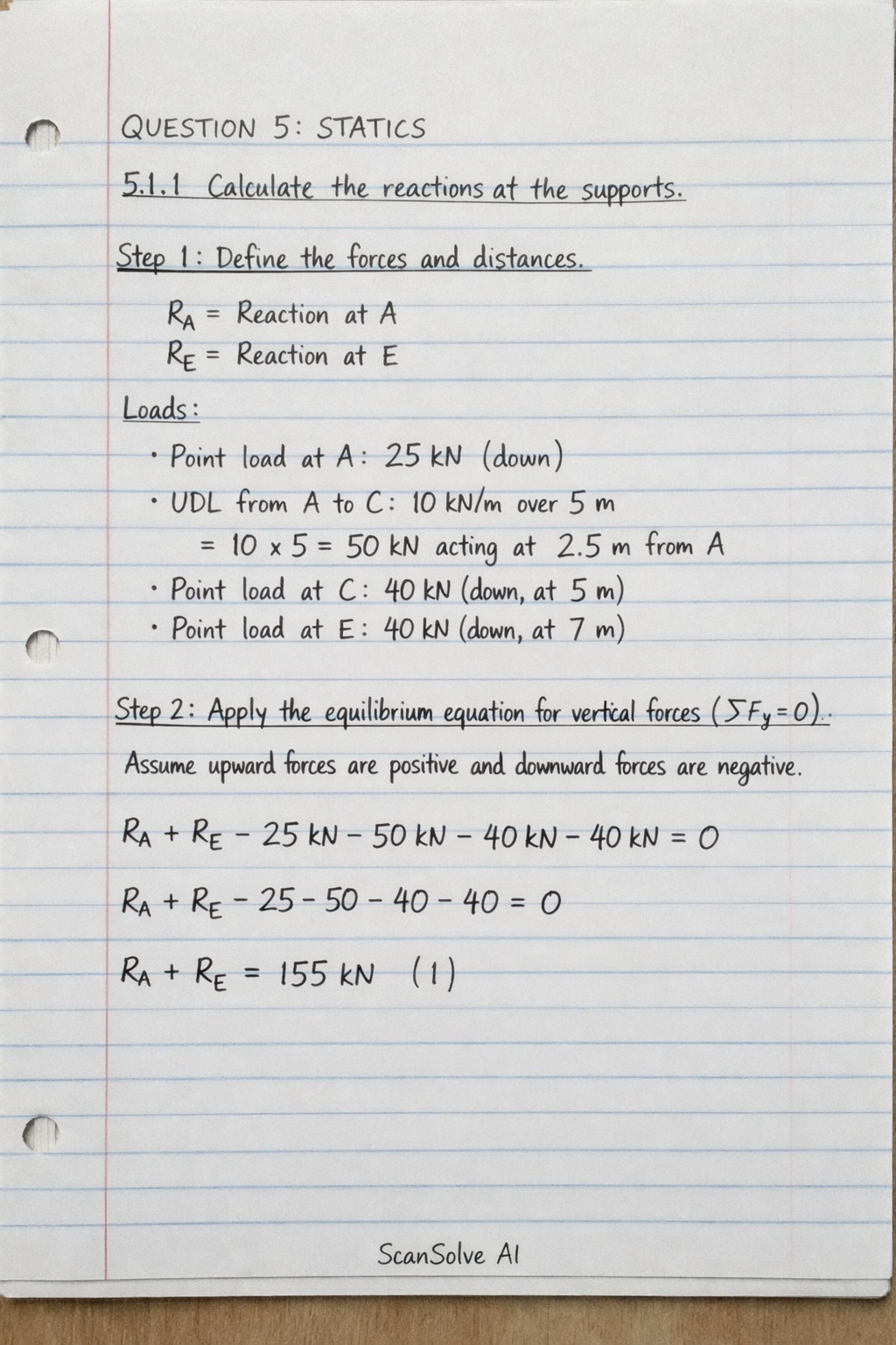
QUESTION 5: STATICS

5.1.1 Calculate the reactions at the supports.

Step 1: Define the forces and distances. The beam has supports at A and E. Let RAR_A and RER_E be the upward reactions at A and E, respectively. Loads:

  • Point load at A: 25 kN25 \text{ kN} (downwards)
  • Uniformly Distributed Load (UDL) from A to C: 10 kN/m10 \text{ kN/m} over 5 m5 \text{ m} (total 10×5=50 kN10 \times 5 = 50 \text{ kN} acting at 2.5 m2.5 \text{ m} from A)
  • Point load at C: 40 kN40 \text{ kN} (downwards, at 5 m5 \text{ m} from A)
  • Point load at E: 40 kN40 \text{ kN} (downwards, at 7 m7 \text{ m} from A)

Step 2: Apply the equilibrium equation for vertical forces (Fy=0\sum F_y = 0). Assume upward forces are positive and downward forces are negative. RA+RE25kN(10kN/m×5m)40kN40kN=0R_A + R_E - 25 kN - (10 kN/m \times 5 m) - 40 kN - 40 kN = 0 RA+RE25504040=0R_A + R_E - 25 - 50 - 40 - 40 = 0 RA+RE=155kN(1)R_A + R_E = 155 kN \quad (1)

Step 3: Apply the equilibrium equation for moments about point A (MA=0\sum M_A = 0). Assume clockwise moments are positive. (10kN/m×5m)×(2.5m)+(40kN×5m)+(40kN×7m)(RE×7m)=0(10 kN/m \times 5 m) \times (2.5 m) + (40 kN \times 5 m) + (40 kN \times 7 m) - (R_E \times 7 m) = 0 (50kN×2.5m)+(200kNm)+(280kNm)7RE=0(50 kN \times 2.5 m) + (200 kNm) + (280 kNm) - 7 R_E = 0 125kNm+200kNm+280kNm7RE=0125 kNm + 200 kNm + 280 kNm - 7 R_E = 0 605kNm7RE=0605 kNm - 7 R_E = 0 7RE=6057 R_E = 605 RE=6057kN86.42857kNR_E = \frac{605}{7} kN \approx 86.42857 kN

Step 4: Substitute RER_E into equation (1) to find RAR_A. RA+86.42857kN=155kNR_A + 86.42857 kN = 155 kN RA=15586.42857kNR_A = 155 - 86.42857 kN RA68.57143kNR_A \approx 68.57143 kN Rounding to three significant figures: RA=68.6 kNR_A = \text{68.6 kN} RE=86.4 kNR_E = \text{86.4 kN}

5.1.2 Calculate the bending moments at B, C and D.

Step 1: Calculate the bending moment at B (at x=1 mx = 1 \text{ m} from A). Consider forces to the left of B. MB=(RA×1m)(25kN×1m)(10kN/m×1m×0.5m)M_B = (R_A \times 1 m) - (25 kN \times 1 m) - (10 kN/m \times 1 m \times 0.5 m) MB=(68.57143×1)(25×1)(10×0.5)M_B = (68.57143 \times 1) - (25 \times 1) - (10 \times 0.5) MB=68.57143255=38.57143kNmM_B = 68.57143 - 25 - 5 = 38.57143 kNm Rounding to three significant figures: MB=38.6 kNmM_B = \text{38.6 kNm}

Step 2: Calculate the bending moment at C (at x=5 mx = 5 \text{ m} from A). Consider forces to the left of C. MC=(RA×5m)(25kN×5m)(10kN/m×5m×(5/2)m)M_C = (R_A \times 5 m) - (25 kN \times 5 m) - (10 kN/m \times 5 m \times (5/2) m) MC=(68.57143×5)(25×5)(50×2.5)M_C = (68.57143 \times 5) - (25 \times 5) - (50 \times 2.5) MC=342.85715125125=92.85715kNmM_C = 342.85715 - 125 - 125 = 92.85715 kNm Rounding to three significant figures: MC=92.9 kNmM_C = \text{92.9 kNm}

Step 3: Calculate the bending moment at D (at x=6 mx = 6 \text{ m} from A). Consider forces to the right of D for simplicity. MD=(RE×1m)(40kN×1m)M_D = (R_E \times 1 m) - (40 kN \times 1 m) MD=(86.42857×1)(40×1)M_D = (86.42857 \times 1) - (40 \times 1) MD=86.4285740=46.42857kNmM_D = 86.42857 - 40 = 46.42857 kNm Rounding to three significant figures: MD=46.4 kNmM_D = \text{46.4 kNm}

5.1.3 Draw the SF and BM diagrams. Also, determine the magnitude of the maximum bending moment and its position.

Shear Force (SF) Diagram:

  • At A (just right): VA=RA25kN=68.5725=43.57 kNV_A = R_A - 25 kN = 68.57 - 25 = 43.57 \text{ kN}.
  • From A to C (UDL): Shear force decreases linearly.
    • At B (just left/right): VB=43.57(10×1)=33.57 kNV_B = 43.57 - (10 \times 1) = 33.57 \text{ kN}.
    • At C (just left): VC,L=43.57(10×5)=6.43 kNV_{C,L} = 43.57 - (10 \times 5) = -6.43 \text{ kN}.
  • At C (just right): VC,R=VC,L40kN=6.4340=46.43 kNV_{C,R} = V_{C,L} - 40 kN = -6.43 - 40 = -46.43 \text{ kN}.
  • From C to E (no UDL): Shear force is constant.
    • At D (just left/right): VD=46.43 kNV_D = -46.43 \text{ kN}.
    • At E (just left): VE,L=46.43 kNV_{E,L} = -46.43 \text{ kN}.
  • At E (just right): VE,R=VE,L+RE40kN=46.43+86.4340=0 kNV_{E,R} = V_{E,L} + R_E - 40 kN = -46.43 + 86.43 - 40 = 0 \text{ kN}.

Bending Moment (BM) Diagram:

  • At A: MA=0 kNmM_A = 0 \text{ kNm}.
  • From A to C (UDL): Bending moment is a parabolic curve.
    • At B: MB=38.6 kNmM_B = 38.6 \text{ kNm}.
    • At C: MC=92.9 kNmM_C = 92.9 \text{ kNm}.
  • From C to E (no UDL): Bending moment is a linear curve.
    • At D: MD=46.4 kNmM_D = 46.4 \text{ kNm}.
  • At E: ME=0 kNmM_E = 0 \text{ kNm}.

Maximum Bending Moment and its Position: The maximum bending moment occurs where the shear force is zero. The shear force changes sign between B and C. The shear force equation for 1m<x<5 m1 m < x < 5 \text{ m} (from A) is V(x)=RA2510x=68.571432510x=43.5714310xV(x) = R_A - 25 - 10x = 68.57143 - 25 - 10x = 43.57143 - 10x. Set V(x)=0V(x) = 0: 43.5714310x=043.57143 - 10x = 0 x=43.5714310=4.357143mfromAx = \frac{43.57143}{10} = 4.357143 m from A Now, calculate the bending moment at this position: Mmax=(RA×x)(25×x)(10×x×x/2)M_{max} = (R_A \times x) - (25 \times x) - (10 \times x \times x/2) Mmax=(68.57143×4.357143)(25×4.357143)(5×(4.357143)2)M_{max} = (68.57143 \times 4.357143) - (25 \times 4.357143) - (5 \times (4.357143)^2) Mmax=298.775108.92857594.9249594.921kNmM_{max} = 298.775 - 108.928575 - 94.92495 \approx 94.921 kNm Rounding to three significant figures: Magnitude of maximum bending moment: 94.9kNm\boxed{94.9 kNm} Position of maximum bending moment: 4.36mfromA\boxed{4.36 m from A}

5.2 Calculate the centre of gravity of the body from the table on which it is placed.

The body consists of a cylinder and a hemisphere (semi-ball) on top. Let the origin be at the base of the cylinder (on the table).

Part 1: Cylinder

  • Diameter = 50 mm50 \text{ mm}, so radius r=25 mmr = 25 \text{ mm}.
  • Height hc=250 mmh_c = 250 \text{ mm}.
  • Volume Vc=πr2hc=π(25mm)2(250mm)=156250πmm3V_c = \pi r^2 h_c = \pi (25 mm)^2 (250 mm) = 156250 \pi mm^3.
  • Centroid from the base yc=hc/2=250mm/2=125 mmy_c = h_c / 2 = 250 mm / 2 = 125 \text{ mm}.

Part 2: Hemisphere

  • Radius r=25 mmr = 25 \text{ mm}.
  • Volume Vh=23πr3=23π(25mm)3=23π(15625)=312503πmm3V_h = \frac{2}{3}\pi r^3 = \frac{2}{3}\pi (25 mm)^3 = \frac{2}{3}\pi (15625) = \frac{31250}{3}\pi mm^3.
  • Centroid from its flat base yh=38r=38(25mm)=9.375 mmy_h' = \frac{3}{8}r = \frac{3}{8}(25 mm) = 9.375 \text{ mm}.
  • The flat base of the hemisphere is at the top of the cylinder, which is 250 mm250 \text{ mm} from the table.
  • Centroid from the table yh=hc+yh=250mm+9.375mm=259.375 mmy_h = h_c + y_h' = 250 mm + 9.375 mm = 259.375 \text{ mm}.

Composite Body Centre of Gravity (Yˉ\bar{Y}): Yˉ=Vcyc+VhyhVc+Vh\bar{Y} = \frac{V_c y_c + V_h y_h}{V_c + V_h} Yˉ=(156250π×125)+(312503π×259.375)156250π+312503π\bar{Y} = \frac{(156250 \pi \times 125) + (\frac{31250}{3}\pi \times 259.375)}{156250 \pi + \frac{31250}{3}\pi} Cancel π\pi from all terms: Yˉ=(156250×125)+(312503×259.375)156250+312503\bar{Y} = \frac{(156250 \times 125) + (\frac{31250}{3} \times 259.375)}{156250 + \frac{31250}{3}} Multiply numerator and denominator by 3 to simplify: Yˉ=(3×156250×125)+(31250×259.375)(3×156250)+31250\bar{Y} = \frac{(3 \times 156250 \times 125) + (31250 \times 259.375)}{(3 \times 156250) + 31250} Yˉ=58593750+8105468.75468750+31250\bar{Y} = \frac{58593750 + 8105468.75}{468750 + 31250} Yˉ=66699218.75500000\bar{Y} = \frac{66699218.75}{500000} Yˉ133.398mm\bar{Y} \approx 133.398 mm Rounding to three significant figures: 133mm\boxed{133 mm}

What's next?

Was this helpful?

Need help with your own homework?

Get instant step-by-step solutions to any question. Free to start.

Ask Your Question
Handwritten step-by-step solution preview

Handwritten Step-by-Step Solution

Get this as a handwritten image on WhatsApp — like a tutor wrote it for you.

Try on WhatsApp

Still have questions?

Quick Answer

QUESTION 5: STATICS 5.1.1 Calculate the reactions at the supports. Step 1: Define the forces and distances.

Consider the loaded beam in FIGURE 1 below and answer the following questions. Calculate the reactions at the supports. Calculate bending moments at B, C and D. Draw the SF and the BM diagrams. Also, determine the magnitude of the maximum bending moment and its position.
Physics

This physics problem tests your understanding of fundamental physical laws and their applications. The step-by-step solution below breaks down the problem using relevant equations and physical reasoning.

ScanSolve AI Answer
QUESTION 5: STATICS 5.1.1 Calculate the reactions at the supports. Step 1: Define the forces and distances. The beam has supports at A and E. Let R_A and R_E be the upward reactions at A and E, respectively. Loads: Point load at A: 25 kN (downwards) Uniformly Distributed Load (UDL) from A to C: 10 kN/m over 5 m (total 10 × 5 = 50 kN acting at 2.5 m from A) Point load at C: 40 kN (downwards, at 5 m from A) Point load at E: 40 kN (downwards, at 7 m from A) Step 2: Apply the equilibrium equation for vertical forces ( F_y = 0). Assume upward forces are positive and downward forces are negative. R_A + R_E - 25 kN - (10 kN/m × 5 m) - 40 kN - 40 kN = 0 R_A + R_E - 25 - 50 - 40 - 40 = 0 R_A + R_E = 155 kN (1) Step 3: Apply the equilibrium equation for moments about point A ( M_A = 0). Assume clockwise moments are positive. (10 kN/m × 5 m) × (2.5 m) + (40 kN × 5 m) + (40 kN × 7 m) - (R_E × 7 m) = 0 (50 kN × 2.5 m) + (200 kNm) + (280 kNm) - 7 R_E = 0 125 kNm + 200 kNm + 280 kNm - 7 R_E = 0 605 kNm - 7 R_E = 0 7 R_E = 605 R_E = (605)/(7) kN ≈ 86.42857 kN Step 4: Substitute R_E into equation (1) to find R_A. R_A + 86.42857 kN = 155 kN R_A = 155 - 86.42857 kN R_A ≈ 68.57143 kN Rounding to three significant figures: R_A = 68.6 kN R_E = 86.4 kN 5.1.2 Calculate the bending moments at B, C and D. Step 1: Calculate the bending moment at B (at x = 1 m from A). Consider forces to the left of B. M_B = (R_A × 1 m) - (25 kN × 1 m) - (10 kN/m × 1 m × 0.5 m) M_B = (68.57143 × 1) - (25 × 1) - (10 × 0.5) M_B = 68.57143 - 25 - 5 = 38.57143 kNm Rounding to three significant figures: M_B = 38.6 kNm Step 2: Calculate the bending moment at C (at x = 5 m from A). Consider forces to the left of C. M_C = (R_A × 5 m) - (25 kN × 5 m) - (10 kN/m × 5 m × (5/2) m) M_C = (68.57143 × 5) - (25 × 5) - (50 × 2.5) M_C = 342.85715 - 125 - 125 = 92.85715 kNm Rounding to three significant figures: M_C = 92.9 kNm Step 3: Calculate the bending moment at D (at x = 6 m from A). Consider forces to the right of D for simplicity. M_D = (R_E × 1 m) - (40 kN × 1 m) M_D = (86.42857 × 1) - (40 × 1) M_D = 86.42857 - 40 = 46.42857 kNm Rounding to three significant figures: M_D = 46.4 kNm 5.1.3 Draw the SF and BM diagrams. Also, determine the magnitude of the maximum bending moment and its position. Shear Force (SF) Diagram: At A (just right): V_A = R_A - 25 kN = 68.57 - 25 = 43.57 kN. From A to C (UDL): Shear force decreases linearly. At B (just left/right): V_B = 43.57 - (10 × 1) = 33.57 kN. At C (just left): V_C,L = 43.57 - (10 × 5) = -6.43 kN. At C (just right): V_C,R = V_C,L - 40 kN = -6.43 - 40 = -46.43 kN. From C to E (no UDL): Shear force is constant. At D (just left/right): V_D = -46.43 kN. At E (just left): V_E,L = -46.43 kN. At E (just right): V_E,R = V_E,L + R_E - 40 kN = -46.43 + 86.43 - 40 = 0 kN. Bending Moment (BM) Diagram: At A: M_A = 0 kNm. From A to C (UDL): Bending moment is a parabolic curve. At B: M_B = 38.6 kNm. At C: M_C = 92.9 kNm. From C to E (no UDL): Bending moment is a linear curve. At D: M_D = 46.4 kNm. At E: M_E = 0 kNm. Maximum Bending Moment and its Position: The maximum bending moment occurs where the shear force is zero. The shear force changes sign between B and C. The shear force equation for 1 m < x < 5 m (from A) is V(x) = R_A - 25 - 10x = 68.57143 - 25 - 10x = 43.57143 - 10x. Set V(x) = 0: 43.57143 - 10x = 0 x = (43.57143)/(10) = 4.357143 m from A Now, calculate the bending moment at this position: M_max = (R_A × x) - (25 × x) - (10 × x × x/2) M_max = (68.57143 × 4.357143) - (25 × 4.357143) - (5 × (4.357143)^2) M_max = 298.775 - 108.928575 - 94.92495 ≈ 94.921 kNm Rounding to three significant figures: Magnitude of maximum bending moment: 94.9 kNm Position of maximum bending moment: 4.36 m from A 5.2 Calculate the centre of gravity of the body from the table on which it is placed. The body consists of a cylinder and a hemisphere (semi-ball) on top. Let the origin be at the base of the cylinder (on the table). Part 1: Cylinder Diameter = 50 mm, so radius r = 25 mm. Height h_c = 250 mm. Volume V_c = r^2 h_c = (25 mm)^2 (250 mm) = 156250 mm^3. Centroid from the base y_c = h_c / 2 = 250 mm / 2 = 125 mm. Part 2: Hemisphere Radius r = 25 mm. Volume V_h = (2)/(3) r^3 = (2)/(3) (25 mm)^3 = (2)/(3) (15625) = (31250)/(3) mm^3. Centroid from its flat base y_h' = (3)/(8)r = (3)/(8)(25 mm) = 9.375 mm. The flat base of the hemisphere is at the top of the cylinder, which is 250 mm from the table. Centroid from the table y_h = h_c + y_h' = 250 mm + 9.375 mm = 259.375 mm. Composite Body Centre of Gravity (Y): Y = (V_c y_c + V_h y_h)/(V_c + V_h) Y = ((156250 × 125) + (31250)/(3) × 259.375)156250 + (31250)/(3) Cancel from all terms: Y = ((156250 × 125) + (31250)/(3) × 259.375)156250 + (31250)/(3) Multiply numerator and denominator by 3 to simplify: Y = ((3 × 156250 × 125) + (31250 × 259.375))/((3 × 156250) + 31250) Y = (58593750 + 8105468.75)/(468750 + 31250) Y = (66699218.75)/(500000) Y ≈ 133.398 mm Rounding to three significant figures: 133 mm What's next?