Mention four methods of reducing leakage fluxes in a transformer.
|Physics
Mention four methods of reducing leakage fluxes in a transformer.
ScanSolve AI Answer
Answer
16.09 A
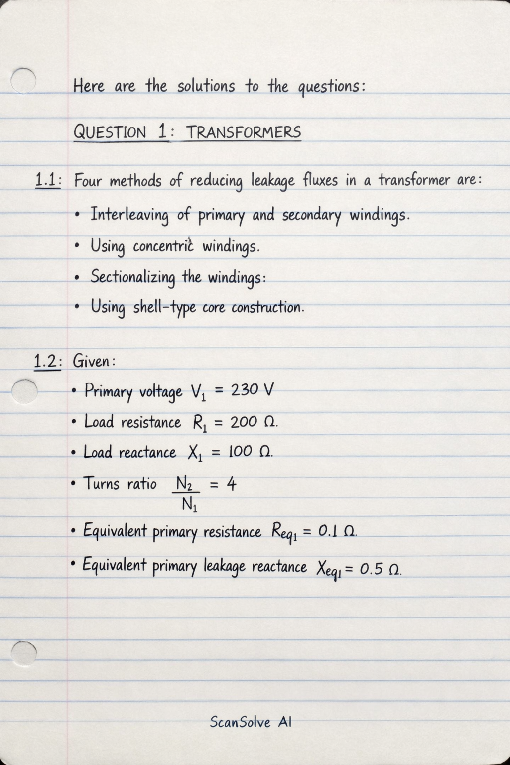
Here are the solutions to the questions:
QUESTION 1: TRANSFORMERS
1.1: Four methods of reducing leakage fluxes in a transformer are:
Interleaving of primary and secondary windings.
Using concentric windings.
Sectionalizing the windings.
Using shell-type core construction.
1.2: Given:
Primary voltage V1=230 V
Load resistance RL=200Ω
Load reactance XL=100Ω
Turns ratio N2/N1=4
Equivalent primary resistance Req1=0.1Ω
Equivalent primary leakage reactance Xeq1=0.5Ω
Step 1: Calculate the load impedance referred to the primary side.
The turns ratio a=N1/N2=1/4.
The load impedance is ZL=RL+jXL=200+j100Ω.
The load impedance referred to the primary is ZL1=a2ZL.
ZL1=(41)2(200+j100)=161(200+j100)=12.5+j6.25Ω
The total equivalent impedance referred to the primary is Ztotal,1=Req1+jXeq1+ZL1.
Ztotal,1=(0.1+j0.5)+(12.5+j6.25)=(0.1+12.5)+j(0.5+6.25)=12.6+j6.75Ω
The magnitude of the total equivalent impedance is:
∣Ztotal,1∣=12.62+6.752=158.76+45.5625=204.3225≈14.294Ω
1.2.1: The primary circulating current (I1).
The primary current is I1=V1/Ztotal,1.
I1=12.6+j6.75Ω230VI1=14.294∠arctan(12.66.75)230=14.294∠28.18∘230≈16.09∠−28.18∘ A
The magnitude of the primary circulating current is:
16.09A
1.2.2: The per unit regulation of the transformer.
The power factor angle ϕ is the angle of Ztotal,1, so ϕ=28.18∘.
cosϕ=cos(28.18∘)≈0.8815sinϕ=sin(28.18∘)≈0.4722
The voltage regulation (VR) is given by:
VR=V1I1(Req1cosϕ+Xeq1sinϕ)VR=23016.09(0.1×0.8815+0.5×0.4722)VR=23016.09(0.08815+0.2361)=23016.09×0.32425=2305.218≈0.02268
The per unit regulation is:
0.02268pu
1.2.3: The secondary terminal voltage (V2).
The voltage across the load referred to the primary is VL1=I1ZL1.
ZL1=12.5+j6.25=12.52+6.252∠arctan(12.56.25)=13.975∠26.565∘ΩVL1=(16.09∠−28.18∘)×(13.975∠26.565∘)VL1=(16.09×13.975)∠(−28.18∘+26.565∘)=224.86∠−1.615∘ V
The secondary terminal voltage V2 is related to VL1 by the turns ratio N2/N1=4.
V2=VL1×N1N2=224.86×4∠−1.615∘=899.44∠−1.615∘ V
The magnitude of the secondary terminal voltage is:
899.44V
QUESTION 2: MEASUREMENT OF POWER IN THREE PHASE SYSTEMS
2.1: Given:
Line voltage VL=440 V
Frequency f=50 Hz
Star connected load
Impedance per phase z=5.2+j6.7Ω/phase
Step 1: Calculate phase voltage, phase current, and power factor.
For a star-connected load, the phase voltage Vp=VL/3.
Vp=3440≈254.03 V
The magnitude of the impedance per phase is ∣z∣=5.22+6.72.
∣z∣=27.04+44.89=71.93≈8.481Ω
The phase current Ip=Vp/∣z∣.
Ip=8.481254.03≈29.95 A
For a star connection, the line current IL=Ip≈29.95 A.
The power factor angle ϕ=arctan(X/R)=arctan(6.7/5.2)≈52.17∘.
The power factor cosϕ=cos(52.17∘)≈0.613.
2.1.1: The total power of the load (PT).
The total power for a three-phase system is PT=3VLILcosϕ.
PT=3×440V×29.95A×0.613PT=13979.8W≈13.98 kW
The total power of the load is:
13.98kW
2.1.2: The readings on watt-meters, if two-wattmeter method is used to measure the power taken by the load.
The two wattmeter readings are W1=VLILcos(30∘−ϕ) and W2=VLILcos(30∘+ϕ).
Here ϕ=52.17∘.
30∘−ϕ=30∘−52.17∘=−22.17∘30∘+ϕ=30∘+52.17∘=82.17∘W1=440×29.95×cos(−22.17∘)=440×29.95×0.926≈12200 WW2=440×29.95×cos(82.17∘)=440×29.95×0.136≈1792 W
The readings on the wattmeters are:
W1=12200W,W2=1792W
2.2: Calculate the resistance per phase of a three phase l=28 km, overhead line with solid conductors of D=1.8 cm diameter, with a symmetrical spacing of d=0.8 m between centres. Take resistivity of the conductor material as ρ=1.7μΩ cm.
Step 1: Convert units and calculate the cross-sectional area.
Length l=28km=28×105 cm.
Diameter D=1.8 cm, so radius r=D/2=0.9 cm.
Resistivity ρ=1.7μΩcm=1.7×10⁻⁶Ω cm.
The cross-sectional area A=πr2.
A=π(0.9cm)2=0.81πcm2
Step 2: Calculate the resistance per phase.
The resistance Rphase is given by the formula R=ρAl.
Rphase=(1.7×10⁻⁶Ωcm)×0.81πcm228×105cmRphase=0.81π1.7×28Ω=2.5446947.6Ω≈18.705Ω
The resistance per phase is:
18.71Ω
QUESTION 3: AC MACHINES
3.1: Given:
Synchronous impedance per phase Zs=1+j6.5Ω/phase.
Open circuit line voltage of one alternator E1,line=2.2kV=2200 V.
Circulating current IC=80 A.
Machines are star-connected and in exact phase opposition.
Step 1: Calculate phase values and magnitude of synchronous impedance.
The phase voltage of the first alternator is E1,phase=E1,line/3.
E1,phase=32200≈1270.17 V
The magnitude of the synchronous impedance is ∣Zs∣=12+6.52.
∣Zs∣=1+42.25=43.25≈6.576Ω
3.1.1: The open circuit voltage of the other machine (E2) assuming it is bigger than that of the first machine.
When two alternators are in parallel and in exact phase opposition, the circulating current IC is given by:
IC=2ZsE2,phase−E1,phase
This formula assumes E1 and E2 are in phase, and E2>E1. However, "exact phase opposition" means E1 and E2 are 180∘ out of phase.
Let E1=E1,phase∠0∘ and E2=E2,phase∠180∘.
The voltage difference driving the circulating current is E1−E2=E1,phase−(−E2,phase)=E1,phase+E2,phase.
The magnitude of the circulating current is ∣IC∣=2∣Zs∣E1,phase+E2,phase.
80A=2×6.576Ω1270.17V+E2,phase80×(2×6.576)=1270.17+E2,phase1052.16=1270.17+E2,phaseE2,phase=1052.16−1270.17=−218.01 V
This result is negative, which contradicts the assumption that E2 is bigger than E1. This indicates that the problem statement "exact phase opposition" might be interpreted differently in the context of the given circulating current value, or there's an inconsistency in the problem data.
A common scenario for circulating current in parallel alternators is due to a phase difference between EMFs, or a difference in magnitudes when EMFs are in phase. If they are in "exact phase opposition", it usually means they are 180∘ out of phase.
If the circulating current is IC=2ZsE1−E2 where E1 and E2 are phasors, and E1=E1,phase∠0∘ and E2=E2,phase∠180∘, then E1−E2=E1,phase−(−E2,phase)=E1,phase+E2,phase.
The magnitude of this voltage difference is E1,phase+E2,phase.
The magnitude of IC is 80 A.
∣IC∣=2∣Zs∣E1,phase+E2,phase.
This leads to E2,phase=−218.01 V, which is not physically possible for a magnitude.
Let's assume "exact phase opposition" means that the resultant voltage causing the circulating current is E2−E1 (phasor difference), and the problem implies that E1 and E2 are in phase but with different magnitudes, and the "phase opposition" refers to the current flow. This is a common source of confusion.
If E1 and E2 are in phase, and E2>E1, then IC=2ZsE2,phase−E1,phase.
∣IC∣=2∣Zs∣E2,phase−E1,phase.
80=2×6.576E2,phase−1270.171052.16=E2,phase−1270.17E2,phase=1052.16+1270.17=2322.33 V
This value is positive and greater than E1,phase, consistent with the problem statement.
The open circuit line voltage of the other machine is E2,line=E2,phase×3.
E2,line=2322.33×3≈4021.9 V
The open circuit voltage of the other machine is:
4.022kV
3.1.2: The terminal voltage (line value).
The terminal voltage VT (phase value) is the voltage at the busbar. It can be calculated using either alternator's EMF and circulating current.
Let'
✂️ That answer was long and got cut off. Reply continue and I'll finish it.
Was this helpful?
Need help with your own homework?
Get instant step-by-step solutions to any question. Free to start.
This physics problem tests your understanding of fundamental physical laws and their applications. The step-by-step solution below breaks down the problem using relevant equations and physical reasoning.
ScanSolve AI Answer
Here are the solutions to the questions: QUESTION 1: TRANSFORMERS 1.1: Four methods of reducing leakage fluxes in a transformer are: Interleaving of primary and secondary windings. Using concentric windings. Sectionalizing the windings. Using shell-type core construction. 1.2: Given: Primary voltage V_1 = 230 V Load resistance R_L = 200 Load reactance X_L = 100 Turns ratio N_2/N_1 = 4 Equivalent primary resistance R_eq1 = 0.1 Equivalent primary leakage reactance X_eq1 = 0.5 Step 1: Calculate the load impedance referred to the primary side. The turns ratio a = N_1/N_2 = 1/4. The load impedance is Z_L = R_L + jX_L = 200 + j100 . The load impedance referred to the primary is Z_L1 = a^2 Z_L. Z_L1 = ((1)/(4))^2 (200 + j100) = (1)/(16) (200 + j100) = 12.5 + j6.25 The total equivalent impedance referred to the primary is Z_total,1 = R_eq1 + jX_eq1 + Z_L1. Z_total,1 = (0.1 + j0.5) + (12.5 + j6.25) = (0.1 + 12.5) + j(0.5 + 6.25) = 12.6 + j6.75 The magnitude of the total equivalent impedance is: |Z_total,1| = sqrt(12.6^2 + 6.75^2) = sqrt(158.76 + 45.5625) = sqrt(204.3225) ≈ 14.294 1.2.1: The primary circulating current (I_1). The primary current is I_1 = V_1 / Z_total,1. I_1 = 230 V12.6 + j6.75 I_1 = (230)/(14.294 (6.75)12.6) = (230)/(14.294 28.18^) ≈ 16.09 -28.18^ A The magnitude of the primary circulating current is: 16.09 A 1.2.2: The per unit regulation of the transformer. The power factor angle is the angle of Z_total,1, so = 28.18^. = (28.18^) ≈ 0.8815 = (28.18^) ≈ 0.4722 The voltage regulation (VR) is given by: VR = I_1 (R_eq1 + X_eq1 )V_1 VR = (16.09 (0.1 × 0.8815 + 0.5 × 0.4722))/(230) VR = (16.09 (0.08815 + 0.2361))/(230) = (16.09 × 0.32425)/(230) = (5.218)/(230) ≈ 0.02268 The per unit regulation is: 0.02268 pu 1.2.3: The secondary terminal voltage (V_2). The voltage across the load referred to the primary is V_L1 = I_1 Z_L1. Z_L1 = 12.5 + j6.25 = sqrt(12.5^2 + 6.25^2) ((6.25)/(12.5)) = 13.975 26.565^ V_L1 = (16.09 -28.18^) × (13.975 26.565^) V_L1 = (16.09 × 13.975) (-28.18^ + 26.565^) = 224.86 -1.615^ V The secondary terminal voltage V_2 is related to V_L1 by the turns ratio N_2/N_1 = 4. V_2 = V_L1 × (N_2)/(N_1) = 224.86 × 4 -1.615^ = 899.44 -1.615^ V The magnitude of the secondary terminal voltage is: 899.44 V QUESTION 2: MEASUREMENT OF POWER IN THREE PHASE SYSTEMS 2.1: Given: Line voltage V_L = 440 V Frequency f = 50 Hz Star connected load Impedance per phase z = 5.2 + j6.7 / phase Step 1: Calculate phase voltage, phase current, and power factor. For a star-connected load, the phase voltage V_p = V_L / sqrt(3). V_p = (440)/(sqrt(3)) ≈ 254.03 V The magnitude of the impedance per phase is |z| = sqrt(5.2^2 + 6.7^2). |z| = sqrt(27.04 + 44.89) = sqrt(71.93) ≈ 8.481 The phase current I_p = V_p / |z|. I_p = (254.03)/(8.481) ≈ 29.95 A For a star connection, the line current I_L = I_p ≈ 29.95 A. The power factor angle = (X/R) = (6.7/5.2) ≈ 52.17^. The power factor = (52.17^) ≈ 0.613. 2.1.1: The total power of the load (P_T). The total power for a three-phase system is P_T = sqrt(3) V_L I_L . P_T = sqrt(3) × 440 V × 29.95 A × 0.613 P_T = 13979.8 W ≈ 13.98 kW The total power of the load is: 13.98 kW 2.1.2: The readings on watt-meters, if two-wattmeter method is used to measure the power taken by the load. The two wattmeter readings are W_1 = V_L I_L (30^ - ) and W_2 = V_L I_L (30^ + ). Here = 52.17^. 30^ - = 30^ - 52.17^ = -22.17^ 30^ + = 30^ + 52.17^ = 82.17^ W_1 = 440 × 29.95 × (-22.17^) = 440 × 29.95 × 0.926 ≈ 12200 W W_2 = 440 × 29.95 × (82.17^) = 440 × 29.95 × 0.136 ≈ 1792 W The readings on the wattmeters are: W_1 = 12200 W, W_2 = 1792 W 2.2: Calculate the resistance per phase of a three phase l = 28 km, overhead line with solid conductors of D = 1.8 cm diameter, with a symmetrical spacing of d = 0.8 m between centres. Take resistivity of the conductor material as = 1.7 cm. Step 1: Convert units and calculate the cross-sectional area. Length l = 28 km = 28 × 10^5 cm. Diameter D = 1.8 cm, so radius r = D/2 = 0.9 cm. Resistivity = 1.7 cm = 1.7 × 10^-6 cm. The cross-sectional area A = r^2. A = (0.9 cm)^2 = 0.81 cm^2 Step 2: Calculate the resistance per phase. The resistance R_phase is given by the formula R = (l)/(A). R_phase = (1.7 × 10^-6 cm) × 28 × 10^5 cm0.81 cm^2 R_phase = (1.7 × 28)/(0.81 ) = (47.6)/(2.54469) ≈ 18.705 The resistance per phase is: 18.71 QUESTION 3: AC MACHINES 3.1: Given: Synchronous impedance per phase Z_s = 1 + j6.5 / phase. Open circuit line voltage of one alternator E_1,line = 2.2 kV = 2200 V. Circulating current I_C = 80 A. Machines are star-connected and in exact phase opposition. Step 1: Calculate phase values and magnitude of synchronous impedance. The phase voltage of the first alternator is E_1,phase = E_1,line / sqrt(3). E_1,phase = (2200)/(sqrt(3)) ≈ 1270.17 V The magnitude of the synchronous impedance is |Z_s| = sqrt(1^2 + 6.5^2). |Z_s| = sqrt(1 + 42.25) = sqrt(43.25) ≈ 6.576 3.1.1: The open circuit voltage of the other machine (E_2) assuming it is bigger than that of the first machine. When two alternators are in parallel and in exact phase opposition, the circulating current I_C is given by: I_C = E_2,phase - E_1,phase2Z_s This formula assumes E_1 and E_2 are in phase, and E_2 > E_1. However, "exact phase opposition" means E_1 and E_2 are 180^ out of phase. Let E_1 = E_1,phase 0^ and E_2 = E_2,phase 180^. The voltage difference driving the circulating current is E_1 - E_2 = E_1,phase - (-E_2,phase) = E_1,phase + E_2,phase. The magnitude of the circulating current is |I_C| = E_1,phase + E_2,phase2|Z_s|. 80 A = 1270.17 V + E_2,phase2 × 6.576 80 × (2 × 6.576) = 1270.17 + E_2,phase 1052.16 = 1270.17 + E_2,phase E_2,phase = 1052.16 - 1270.17 = -218.01 V This result is negative, which contradicts the assumption that E_2 is bigger than E_1. This indicates that the problem statement "exact phase opposition" might be interpreted differently in the context of the given circulating current value, or there's an inconsistency in the problem data. A common scenario for circulating current in parallel alternators is due to a phase difference between EMFs, or a difference in magnitudes when EMFs are in phase. If they are in "exact phase opposition", it usually means they are 180^ out of phase. If the circulating current is I_C = (E_1 - E_2)/(2Z_s) where E_1 and E_2 are phasors, and E_1 = E_1,phase 0^ and E_2 = E_2,phase 180^, then E_1 - E_2 = E_1,phase - (-E_2,phase) = E_1,phase + E_2,phase. The magnitude of this voltage difference is E_1,phase + E_2,phase. The magnitude of I_C is 80 A. |I_C| = E_1,phase + E_2,phase2|Z_s|. This leads to E_2,phase = -218.01 V, which is not physically possible for a magnitude. Let's assume "exact phase opposition" means that the resultant voltage causing the circulating current is E_2 - E_1 (phasor difference), and the problem implies that E_1 and E_2 are in phase but with different magnitudes, and the "phase opposition" refers to the current flow. This is a common source of confusion. If E_1 and E_2 are in phase, and E_2 > E_1, then I_C = E_2,phase - E_1,phase2Z_s. |I_C| = E_2,phase - E_1,phase2|Z_s|. 80 = E_2,phase - 1270.172 × 6.576 1052.16 = E_2,phase - 1270.17 E_2,phase = 1052.16 + 1270.17 = 2322.33 V This value is positive and greater than E_1,phase, consistent with the problem statement. The open circuit line voltage of the other machine is E_2,line = E_2,phase × sqrt(3). E_2,line = 2322.33 × sqrt(3) ≈ 4021.9 V The open circuit voltage of the other machine is: 4.022 kV 3.1.2: The terminal voltage (line value). The terminal voltage V_T (phase value) is the voltage at the busbar. It can be calculated using either alternator's EMF and circulating current. Let' ✂️ _That answer was long and got cut off. Reply continue and I'll finish it._