
This physics problem tests your understanding of fundamental physical laws and their applications. The step-by-step solution below breaks down the problem using relevant equations and physical reasoning.
ScanSolve AI Answer
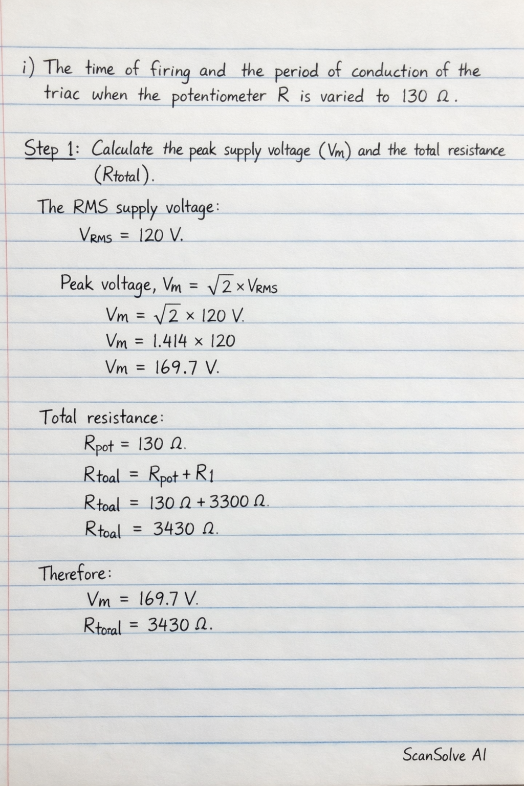
Here is the complete solution for the practical problem: Part a) The components of the circuit of figure 5 are: R_pot = 3.3 k, C = 0.1 , diac ST2 (V_BO = 32V). The supply voltage is 120V, 60Hz. Calculate: i) The time of firing and the period of conduction of the triac when the potentiometer R, is varied to 130 . Step 1: Calculate the peak supply voltage (V_m) and the total resistance (R_total). The RMS supply