
This physics problem tests your understanding of fundamental physical laws and their applications. The step-by-step solution below breaks down the problem using relevant equations and physical reasoning.
ScanSolve AI Answer
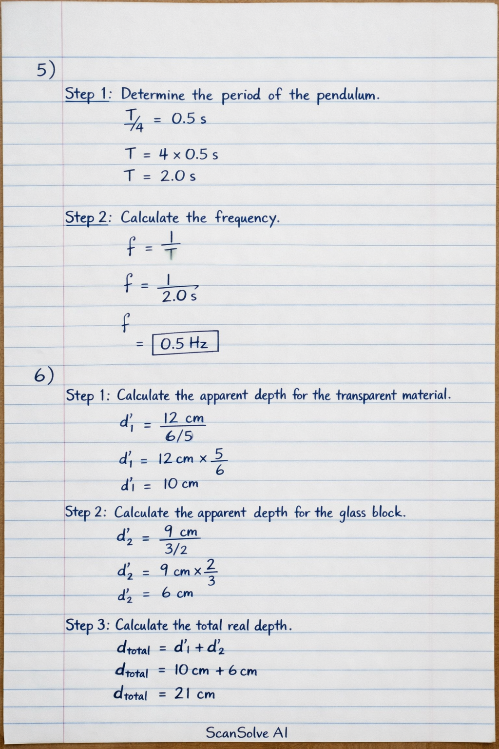
You're on a roll — 5) Step 1: Determine the period of the pendulum. The time taken to move from the mean position to a maximum displacement is one-quarter of a full oscillation. (T)/(4) = 0.5 s T = 4 × 0.5 s T = 2.0 s Step 2: Calculate the frequency. Frequency (f) is the reciprocal of the period (T). f = (1)/(T) f = (1)/(2.0 s) f = 0.5 Hz 6) Step 1: Calculate the apparent depth for the transparent material. The formula for apparent depth (d') is d' = (d)/(n), where d is the real depth and n is the refractive index. For the transparent material: d'_1 = 12 cm6/5 d'_1 = 12 cm × (5)/(6) d'_1 = 10 cm Step 2: Calculate the apparent depth for the glass block. For the glass block: d'_2 = 9 cm3/2 d'_2 = 9 cm × (2)/(3) d'_2 = 6 cm Step 3: Calculate the total real depth. d_total = d_1 + d_2 = 12 cm + 9 cm = 21 cm Step 4: Calculate the total apparent depth. d'_total = d'_1 + d'_2 = 10 cm + 6 cm = 16 cm Step 5: Calculate the vertical displacement of the object. Vertical displacement is the difference between the total real depth and the total apparent depth. Vertical displacement = d_total - d'_total Vertical displacement = 21 cm - 16 cm Vertical displacement = 5 cm 7) To reverse bias a diode, the positive terminal of the dry cell is connected to the cathode (the bar side of the diode symbol), and the negative terminal is connected to the anode (the triangle side of the diode symbol). [scale=0.8] % Dry cell (0,0) to (0,0.5); [line width=1.5pt] (0,0.5) to (0,0.8); % Positive terminal (0,0) to (0,-0.5); [line width=0.5pt] (0,-0.5) to (0,-0.8); % Negative terminal at (0.5, 0.65) +; at (0.5, -0.65) -; % Wires (0,0.8) -- (2,0.8); (0,-0.8) -- (2,-0.8); % Diode (reverse biased) (2,0.8) -- (3,0.8); (3,-0.8) -- (2,-0.8); (3,0.8) -- (3,-0.8); % Cathode bar [fill=white] (3,0) -- (2,0.8) -- (2,-0.8) -- cycle; % Anode triangle at (2.5, 0) ; % Arrow for diode direction % Connecting wires (3,0.8) -- (4,0.8); (3,-0.8) -- (4,-0.8); 8) Step 1: Determine the object and image distances using magnification. The image is real and half the size of the object, so the magnification (M) is -(1)/(2) (negative for a real, inverted image). M = (v)/(u) = -(1)/(2) For a real image formed by a converging lens, u and v are positive distances. The negative sign in magnification indicates inversion. So, the magnitude of the image distance is half the magnitude of the object distance: v = (u)/(2) The distance between the object and the image is 450 mm. For a real image, the object and image are on opposite sides of the lens, so the distance between them is u+v. u + v = 450 mm Step 2: Solve for u and v. Substitute v = (u)/(2) into the equation: u + (u)/(2) = 450 mm (3u)/(2) = 450 mm u = (450 × 2)/(3) mm u = 300 mm Now find v: v = (u)/(2) = 300 mm2 v = 150 mm Step 3: Use the lens formula to find the focal length (f). For a converging lens forming a real image, the lens formula is: (1)/(f) = (1)/(u) + (1)/(v) (1)/(f) = (1)/(300 mm) + (1)/(150 mm) Find a common denominator: (1)/(f) = (1)/(300 mm) + (2)/(300 mm) (1)/(f) = (3)/(300 mm) (1)/(f) = (1)/(100 mm) f = 100 mm Send me the next one 📸