
We read your photo as:
AUTOMATIC AUTO-TRANSFORMER STARTER
Computer Science
ScanSolve AI Answer
Step-by-step solution
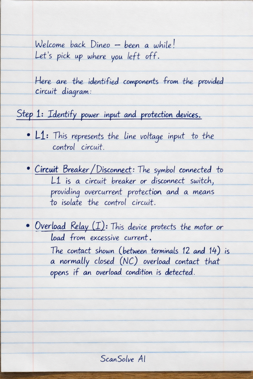
3 stepsHere are the identified components from the provided circuit diagram:
Identify power input and protection devices.
- L1: This represents the line voltage input to the control circuit.
- Circuit Breaker/Disconnect: The symbol connected to L1 is a circuit breaker or disconnect switch, providing overcurrent protection and a means to isolate the control circuit.
- Overload Relay (I): This device protects the motor or load from excessive current. The contact shown (between terminals 12 and 14) is a normally closed (NC) overload contact that opens if an overload condition is detected.
Identify control input devices (push buttons).
- Emergency Stop (ES): This is a normally closed (NC) push button used for immediate shutdown of the system in an emergency.
- STOP Button: This is a normally closed (NC) push button used for routine stopping of the circuit.
- START Button: This is a normally open (NO) push button used to initiate the operation of the circuit.
Identify control logic contacts and output.
- Main Contactor (M) Auxiliary Contact: This is a normally open (NO) contact associated with the main contactor 'M'. It typically serves as a holding contact (or seal-in contact) to maintain the circuit's energized state after the START button is released.
- Timer (T) Contact: This is a normally open (NO) time-delay contact, which will change state after a set period once its associated timer coil is energized. It's used for sequencing operations.
- RUN Indicator/Coil: This represents either a pilot light indicating the "RUN" status of the system or the coil of a relay/contactor that controls the "RUN" state of the auto-transformer.
The handwritten notes (53-19) and (43-29) likely indicate cross-references or connections to other parts of the complete circuit diagram.
Was this helpful?
Still stuck on this one?
Ask a follow-up, and the answer starts from this question.
Got a different question?Ask your own question
More Computer Science Questions
Handwritten Step-by-Step Solution
Get this as a handwritten image on WhatsApp — like a tutor wrote it for you.
Try on WhatsApp