
We read your photo as:
Across a 100 V, 50 Hz supply, a coil with a resistance of 10 and an inductance of 210 mH is connected in series with a variable capacitor. Calculate:
ScanSolve AI Answer
Answers
6 partsStep-by-step solution
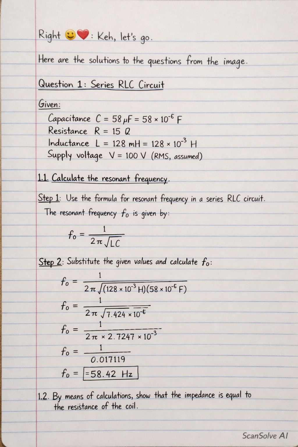
12 stepsHere are the solutions to the questions from the image.
Part 1
Series RLC Circuit
Given:
Capacitance
Resistance
Inductance
Supply voltage (RMS, assumed)
Part 1.1
Calculate the resonant frequency.
Use the formula for resonant frequency in a series RLC circuit.
The resonant frequency is given by:
Substitute the given values and calculate .
Part 1.2
By means of calculations, show that the impedance is equal to the resistance of the coil.
Calculate the inductive reactance () and capacitive reactance () at the resonant frequency .
(Note: The slight difference between and is due to rounding . If is used with full precision, they would be equal.)
Calculate the total impedance of the series RLC circuit.
Using the calculated values:
Since , the impedance is approximately equal to the resistance at resonance.
This shows that at resonance.
Part 1.3
Draw the phasor diagram.
(Since I cannot draw an image, I will describe the key features of the phasor diagram at resonance).
- The current phasor () is typically drawn along the positive x-axis (reference).
- The voltage across the resistor () is in phase with the current, so is also along the positive x-axis.
- The voltage across the inductor () leads the current by , so points along the positive y-axis.
- The voltage across the capacitor () lags the current by , so points along the negative y-axis.
- At resonance, and are equal in magnitude and opposite in direction, so they cancel each other out.
- The total supply voltage () is equal to and is in phase with the current. The diagram would show and on the positive x-axis, on the positive y-axis, and on the negative y-axis, with and having equal lengths. The resultant voltage would coincide with .
Part 2
Parallel RLC Circuit (Implied)
Given:
Coil resistance
Coil inductance
Part 2.1
Determine the frequency at which the resulting current is in phase with the source voltage.
Assumption: This question implies a parallel resonant circuit where the coil (R and L in series) is connected in parallel with a capacitor. However, the value of the capacitor is not provided in the question. Without the capacitor value, it is not possible to calculate a specific non-zero resonant frequency.
If the circuit consists only of the coil (R and L in series) connected to the source, the current will always lag the voltage at any non-zero frequency. The current would only be in phase with the voltage if the circuit were purely resistive, which means the inductance would have to be zero or the frequency would have to be zero (DC).
Therefore, based on the information given, this question cannot be solved for a non-zero frequency.
Missing information: Value of the parallel capacitor.
Part 2.2
Calculate the related Q factor value.
The Q factor (Quality factor) for a parallel resonant circuit where the coil (R and L in series) is in parallel with a capacitor is given by:
or
Since the resonant frequency (or ) cannot be determined without the capacitor value (as explained in 2.1), the Q factor also cannot be calculated.
Missing information: Value of the parallel capacitor (and thus resonant frequency).
Part 3
Series RLC Circuit with Variable Capacitor
Given:
Supply voltage (RMS, assumed)
Supply frequency
Coil resistance
Coil inductance
A variable capacitor is connected in series.
Part 3.1
Capacitance required to produce resonance.
Use the formula for resonant frequency in a series RLC circuit.
At resonance, .
Rearrange the formula to solve for .
Substitute the given values and calculate .
Part 3.2
Value of the capacitor.
This is the same as Question 3.1.
The value of the capacitor is .
Part 3.3
Voltage drop across the coil and capacitor.
Calculate the inductive reactance () and capacitive reactance () at resonance.
At resonance, .
So, .
Calculate the total current () in the series circuit at resonance.
At resonance, the impedance .
Calculate the voltage drop across the coil () and the capacitor ().
The coil has resistance and inductance . The voltage drop across the coil is , where .
The voltage drop across the capacitor is .
Part 3.46.60
Quality factor.
Use the formula for the Q factor of a series RLC circuit.
or
Substitute the values for and .
Still stuck on this one?
Ask a follow-up, and the answer starts from this question.
More Physics Questions
Handwritten Step-by-Step Solution
Get this as a handwritten image on WhatsApp — like a tutor wrote it for you.
Try on WhatsApp