
Create a practical note on beam experiment With title, aim, apparatus, theory, procedure, calculation, table and precautions note
ScanSolve AI Answer
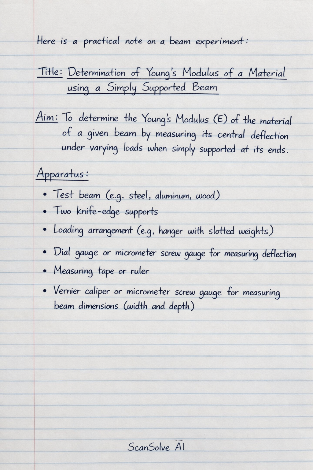
Here is a practical note on a beam experiment:
Title: Determination of Young's Modulus of a Material using a Simply Supported Beam
Aim: To determine the Young's Modulus () of the material of a given beam by measuring its central deflection under varying loads when simply supported at its ends.
Apparatus:
- Test beam (e.g., steel, aluminum, wood)
- Two knife-edge supports
- Loading arrangement (e.g., hanger with slotted weights)
- Dial gauge or micrometer screw gauge for measuring deflection
- Measuring tape or ruler
- Vernier caliper or micrometer screw gauge for measuring beam dimensions (width and depth)
Theory:
When a beam is simply supported at its ends and subjected to a central point load, it undergoes deflection. For a simply supported beam of length with a central point load , the maximum deflection () at the center is given by the formula:
Where:
- is the applied central load (in Newtons, N)
- is the effective length of the beam between the supports (in meters, m)
- is the Young's Modulus of the beam material (in Pascals, Pa or )
- is the moment of inertia of the beam's cross-section (in )
For a rectangular cross-section beam with width and depth :
Substituting into the deflection formula, we get:
From this, Young's Modulus can be calculated as:
By plotting a graph of load () versus deflection (), a straight line should be obtained. The slope of this graph is . Therefore, can also be determined from the slope () as:
where .
Procedure:
- Measure the width () and depth () of the beam's cross-section using a Vernier caliper or micrometer screw gauge at several points and record the average values.
- Place the beam on the two knife-edge supports, ensuring they are at the same level.
- Measure the effective length () between the knife-edge supports.
- Position the loading hanger exactly at the center of the beam.
- Place the dial gauge (or micrometer screw gauge) directly under the center of the beam, ensuring its stem touches the beam. Adjust the dial gauge to read zero or a convenient initial reading.
- Apply a small initial load (e.g., ) to ensure the beam is in contact with the supports and the dial gauge. Record this initial load and the corresponding deflection reading.
- Incrementally add weights to the hanger (e.g., or at a time). For each added load, record the total load () and the corresponding deflection () from the dial gauge.
- Continue adding weights until the maximum safe load for the beam is reached or a significant deflection is observed.
- After reaching the maximum load, incrementally remove the weights and record the deflection readings for decreasing loads. This helps check for hysteresis and permanent deformation.
- Plot a graph of total load () versus central deflection ().
Calculation:
- Calculate the average width () and depth () of the beam.
- Calculate the moment of inertia () for the beam's cross-section.
- From the graph, determine the slope () of the linear portion.
- Calculate Young's Modulus () using the formula: Alternatively, for each load-deflection pair, calculate and then find the average .
Table:
| S.No. | Load (W) (N) | Dial Gauge Reading (mm) | Deflection () (mm) | Deflection () (m) |
|---|---|---|---|---|
| 1 | Initial Load | |||
| 2 | ||||
| 3 | ||||
| ... | ... | ... | ... | ... |
| n |
Beam Dimensions:
- Length () =
- Width () =
- Depth () =
Precautions:
- Ensure the knife-edge supports are perfectly level and parallel to each other to prevent twisting of the beam.
- The load should be applied gradually and centrally to avoid eccentric loading.
- The dial gauge should be placed directly under the point of load application to measure maximum deflection accurately.
- Avoid exceeding the elastic limit of the beam material to prevent permanent deformation.
- Take readings carefully, ensuring the dial gauge stem is perpendicular to the beam surface.
- Measure the beam dimensions (, , ) accurately using appropriate measuring instruments.
- Ensure there is no slack in the loading arrangement before taking initial readings.
Still stuck on this one?
Ask a follow-up, and the answer starts from this question.
More Physics Questions
Handwritten Step-by-Step Solution
Get this as a handwritten image on WhatsApp — like a tutor wrote it for you.
Try on WhatsApp