
We read your photo as:
Identify the bridge circuit.
Physics
ScanSolve AI Answer
This answer stops before the end.
It was cut off when it was first written. Ask ScanSolve this question again for the full working.
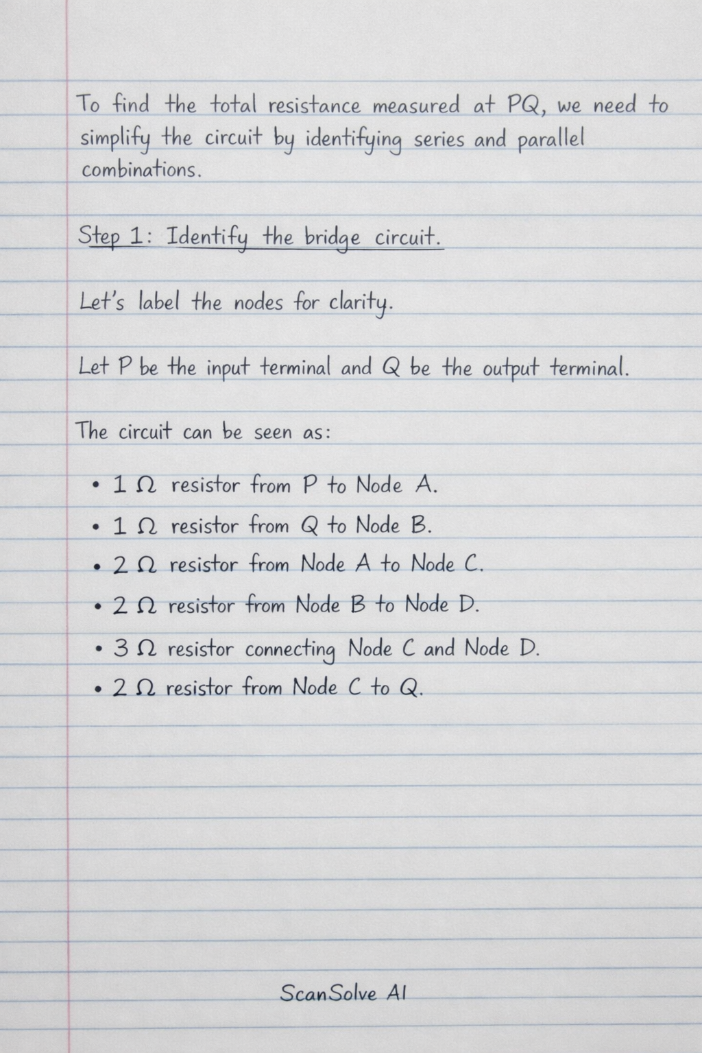
To find the total resistance measured at PQ, we need to simplify the circuit by identifying series and parallel combinations.
Step 1: Identify the bridge circuit.
Let's label the nodes for clarity.
Let P be the input terminal and Q be the output terminal.
The circuit can be seen as:
- A resistor from P to Node A.
- A resistor from Q to Node B.
- A resistor from Node A to Node C.
- A resistor from Node B to Node D.
- A resistor connecting Node C and Node D.
- A resistor from Node C to Q.
Was this helpful?
Still stuck on this one?
Ask a follow-up, and the answer starts from this question.
Got a different question?Ask your own question
More Physics Questions
QIdentify the type of circuit.QIdentify the circuit configuration.QWith the aid of a circuit diagram, explain the functioning of a Bridge rectifier circuit.QIdentify the circuit components and their values.QThe circuit is an unbalanced Wheatstone bridge.
Browse by topic:Electrical Engineering
Handwritten Step-by-Step Solution
Get this as a handwritten image on WhatsApp — like a tutor wrote it for you.
Try on WhatsApp