

This physics problem tests your understanding of fundamental physical laws and their applications. The step-by-step solution below breaks down the problem using relevant equations and physical reasoning.
ScanSolve AI Answer
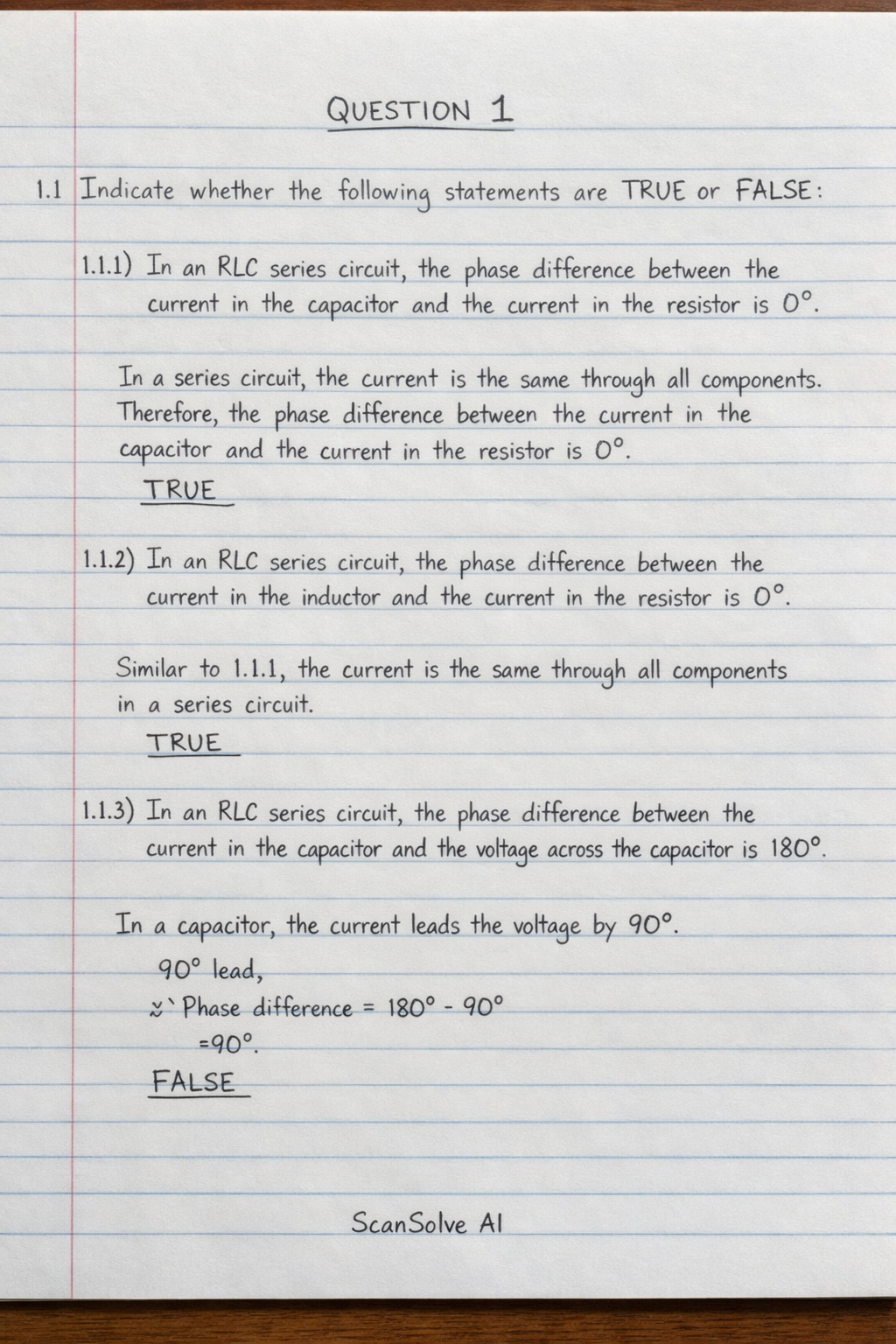
Here are the solutions to your questions: QUESTION 1 1.1 Indicate whether the following statements are TRUE or FALSE: 1.1.1 In an RLC series circuit, the phase difference between the current in the capacitor and the current in the resistor is 0^. In a series circuit, the current is the same through all components. Therefore, the phase difference between the current in the capacitor and the current in the resistor is 0^. TRUE 1.1.2 In an RLC series circuit, the phase difference between the current in the inductor and the current in the resistor is 0^. Similar to 1.1.1, the current is the same through all components in a series circuit. TRUE 1.1.3 In an RLC series circuit, the phase difference between the current in the capacitor and voltage across the capacitor is 180^. In a capacitor, the current leads the voltage by 90^. FALSE 1.1.4 Above the resonance frequency, the current in the inductor lags the voltage in an RLC series circuit. In an inductor, the current always lags the voltage by 90^, regardless of the frequency. TRUE 1.1.5 Below the resonance frequency, the current in the capacitor lags the voltage in an RLC series circuit. In a capacitor, the current always leads the voltage by 90^, regardless of the frequency. FALSE 1.2 Explain what will happen in an RL series circuit if the following happens: 1.2.1 The resistor is open If the resistor is open, the circuit becomes an open circuit, and no current will flow through it. 1.2.2 The inductor is open If the inductor is open, the circuit becomes an open circuit, and no current will flow through it. 1.2.3 A shorted winding on the inductor A shorted winding on the inductor will decrease its effective inductance. This leads to a decrease in inductive reactance (X_L), causing an increase in the total current flowing through the circuit. 1.3 A circuit consists of an 80 \, resistor, a 400 \, mH inductor and a 47 \, capacitor, all connected in parallel across a 240 \, V, 50 \, Hz supply. Step 1: Calculate the inductive and capacitive reactances. Given: R = 80 \, , L = 400 \, mH = 0.4 \, H, C = 47 \, = 47 × 10^-6 \, F, V = 240 \, V, f = 50 \, Hz. Inductive reactance (X_L): X_L = 2 f L X_L = 2 (50 \, Hz) (0.4 \, H) X_L ≈ 125.66 \, Capacitive reactance (X_C): X_C = (1)/(2 f C) X_C = (1)/(2 (50 \, Hz)) (47 × 10^-6 \, F) X_C ≈ 67.73 \, 1.3.1 The current flowing in each branch Step 2: Calculate the current through each branch. Current through the resistor (I_R): I_R = (V)/(R) I_R = 240 \, V80 \, I_R = 3.00 \, A Current through the inductor (I_L): I_L = (V)/(X_L) I_L = 240 \, V125.66 \, I_L ≈ 1.91 \, A Current through the capacitor (I_C): I_C = (V)/(X_C) I_C = 240 \, V67.73 \, I_C ≈ 3.54 \, A 1.3.2 The supply current Step 3: Calculate the total supply current. In a parallel AC circuit, the total current (I_S) is the phasor sum of the individual branch currents. I_S = sqrt(I_R^2 + (I_C - I_L)^2) I_S = sqrt((3.00 \, A))^2 + (3.54 \, A - 1.91 \, A)^2 I_S = sqrt(9.00 + (1.63)^2) I_S = sqrt(9.00 + 2.6569) I_S = sqrt(11.6569) I_S ≈ 3.41 \, A QUESTION 2 2.1 Calculate the oscillation frequency of a Colpitts oscillator if the following values are given: L = 5 \, , C_1 = 0.01 \, and C_2 = 0.002 \, . Step 1: Convert units and calculate the equivalent capacitance (C_eq). Given: L = 5 \, = 5 × 10^-6 \, H C_1 = 0.01 \, = 0.01 × 10^-6 \, F = 10 × 10^-9 \, F C_2 = 0.002 \, = 0.002 × 10^-6 \, F = 2 × 10^-9 \, F For a Colpitts oscillator, C_1 and C_2 are in series for the resonant frequency calculation: C_eq = (C_1 C_2)/(C_1 + C_2) C_eq = (10 × 10^-9 \, F) × (2 × 10^-9 \, F)(10 × 10^-9 \, F) + (2 × 10^-9 \, F) C_eq = 20 × 10^-18 \, F^212 × 10^-9 \, F C_eq ≈ 1.6667 × 10^-9 \, F Step 2: Calculate the oscillation frequency (f). The oscillation frequency for a Colpitts oscillator is: f = (1)/(2(L C_eq)) f = (1)/(2((5 × 10^-6) \, H)) × (1.6667 × 10^-9 \, F) f = (1)/(2(8.3335 × 10^-15)) f = (1)/(2 × 9.1288 × 10^-8) f ≈ 1.743 × 10^6 \, Hz f ≈ 1.743 \, MHz 2.2 Make a drawing of a 555 timer in astable mode. As an AI, I cannot create drawings. However, a 555 timer in astable mode typically consists of: A 555 timer IC. Two resistors (R_A and R_B) connected in series between Vcc and the discharge pin (pin 7). A capacitor (C) connected between the discharge pin (pin 7) and ground, with its other terminal connected to the trigger (pin 2) and threshold (pin 6) pins. The reset pin (pin 4) is connected to Vcc. The control voltage pin (pin 5) is connected to ground via a small capacitor (e.g., 0.01 \, ) for noise filtering. The output is taken from pin 3. 2.3 Name FOUR factors that affect oscillation frequency. Resistance (R) values Capacitance (C) values Inductance (L) values Temperature 2.4 State TWO applications of a monostable multivibrator. Pulse generation (to produce a single output pulse of a specific duration) Delay circuits (to introduce a specific time delay) 2.5 Explain TWO ways in which an SCR (silicon-controlled rectifier) can be turned ON. Gate triggering: Applying a positive voltage pulse to the gate terminal (G) with respect to the cathode (K) when the anode (A) is positive with respect to the cathode. Forward breakover voltage triggering: Increasing the forward anode-cathode voltage beyond the SCR's forward breakover voltage (V_BO), causing it to conduct even without a gate signal. 2.6 Various options are given as possible answers to the following questions. Choose the answer and write only the letter (A–D) next to the question number (2.6.1–2.6.5) in the ANSWER BOOK. 2.6.1 In an LC oscillator circuit, when the capacitor is at its maximum, the inductor is at its minimum. When the capacitor is fully charged (maximum voltage and maximum stored electric energy), the current flowing through the inductor is momentarily zero. Therefore, the magnetic energy stored in the inductor (1/2 L I^2) is at its minimum. A) energy That's 2 down. 3 left today — send the next one.