
This physics problem tests your understanding of fundamental physical laws and their applications. The step-by-step solution below breaks down the problem using relevant equations and physical reasoning.
ScanSolve AI Answer
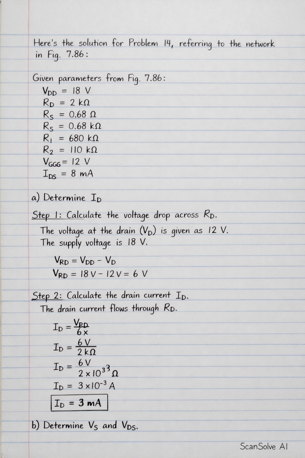
Here's the solution for Problem 14, referring to the network in Fig. 7.86: Given parameters from Fig. 7.86: Supply voltage V_DD = 18 V Drain resistor R_D = 2 k Source resistor R_S = 0.68 k Gate resistor R_1 = 680 k Gate resistor R_2 = 110 k Gate bias voltage source V_GG = 12 V Drain voltage V_D = 12 V JFET parameter I_DSS = 8 mA a) Determine I_D Step 1: Calculate the voltage drop across R_D. The voltage at the drain (V_D) is given as 12 V. The supply voltage is 18 V. V_R_D = V_DD - V_D V_R_D = 18 V - 12 V = 6 V Step 2: Calculate the drain current I_D. The drain current flows through R_D. I_D = V_R_DR_D I_D = 6 V2 k = 6 V2 × 10^3 = 3 × 10^-3 A I_D = 3 mA b) Determine V_S and V_DS Step 1: Calculate the source voltage V_S. The source voltage is the voltage drop across R_S due to I_D. V_S = I_D × R_S V_S = 3 mA × 0.68 k = (3 × 10^-3 A) × (0.68 × 10^3 ) V_S = 2.04 V Step 2: Calculate the drain-source voltage V_DS. V_DS = V_D - V_S V_DS = 12 V - 2.04 V V_DS = 9.96 V c) Determine V_G and V_GS Step 1: Calculate the gate voltage V_G. V_G is determined by the voltage divider formed by R_1 and R_2 connected to the 12 V source. V_G = V_GG × (R_2)/(R_1 + R_2) V_G = 12 V × 110 k680 k + 110 k V_G = 12 V × 110 k790 k = 12 V × (11)/(79) V_G ≈ 1.671 V Step 2: Calculate the gate-source voltage V_GS. V_GS = V_G - V_S V_GS = 1.670886 V - 2.04 V V_GS ≈ -0.369 V d) Determine V_P Step 1: Use the Shockley equation to find V_P. The Shockley equation relates I_D, I_DSS, V_GS, and V_P: I_D = I_DSS (1 - V_GSV_P)^2 Rearrange the equation to solve for V_P: sqrt((I_D)/(I_DSS)) = 1 - V_GSV_P V_GSV_P = 1 - sqrt((I_D)/(I_DSS)) V_P = V_GS1 - sqrt((I_D)/(I_DSS)) Step 2: Substitute the known values. V_P = -0.3691139 V1 - sqrt(3 mA)8 mA V_P = -0.3691139 V1 - sqrt(0.375) V_P = -0.3691139 V1 - 0.6123724 V_P = -0.3691139 V0.3876276 V_P ≈ -0.952 V That's 2 down. 3 left today — send the next one.