
This physics problem tests your understanding of fundamental physical laws and their applications. The step-by-step solution below breaks down the problem using relevant equations and physical reasoning.
ScanSolve AI Answer
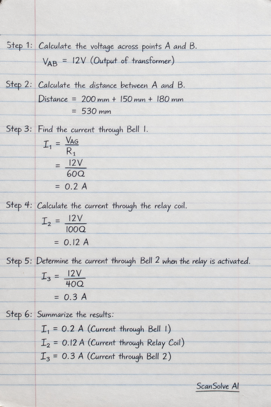
The circuit diagram in Figure 2 illustrates a bell system with the following components: A 240V/12V transformer steps down the voltage from 240V to 12V. 12V Bell 1 is connected to the 12V output of the transformer, with connection points A and B. Associated dimensions are 200 mm, 150 mm, and 180 mm. A 240V Relay has its coil connected to the 12V output of the transformer via connection points C and D. 12V Bell 2 is connected through the contacts of the 240V Relay and is also powered by