
This physics problem tests your understanding of fundamental physical laws and their applications. The step-by-step solution below breaks down the problem using relevant equations and physical reasoning.
ScanSolve AI Answer
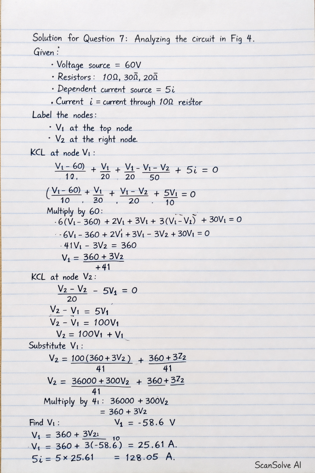
Here's a step-by-step solution for question 7, analyzing the circuit in Fig 4. The circuit in Fig 4 has a 60V voltage source, a 10Ω resistor, a 30Ω resistor, a 20Ω resistor, and a dependent current source 5i. The current i is defined as the current flowing through the 10Ω resistor from left to right. Let's label the nodes: Let the bottom wire be the reference node (0V). Let the node between the 10Ω, 30Ω, and 20Ω resistors be V_1. Let the node to the right of the 30Ω resistor and above the