
We read your photo as:
Use simple diagram to explain Thevenin's theorem. For the network shown in fig. Q3b below, calculate the current in the 92 resistor using Thevenin's theorem.
ScanSolve AI Answer
This answer stops before the end.
It was cut off when it was first written. Ask ScanSolve this question again for the full working.
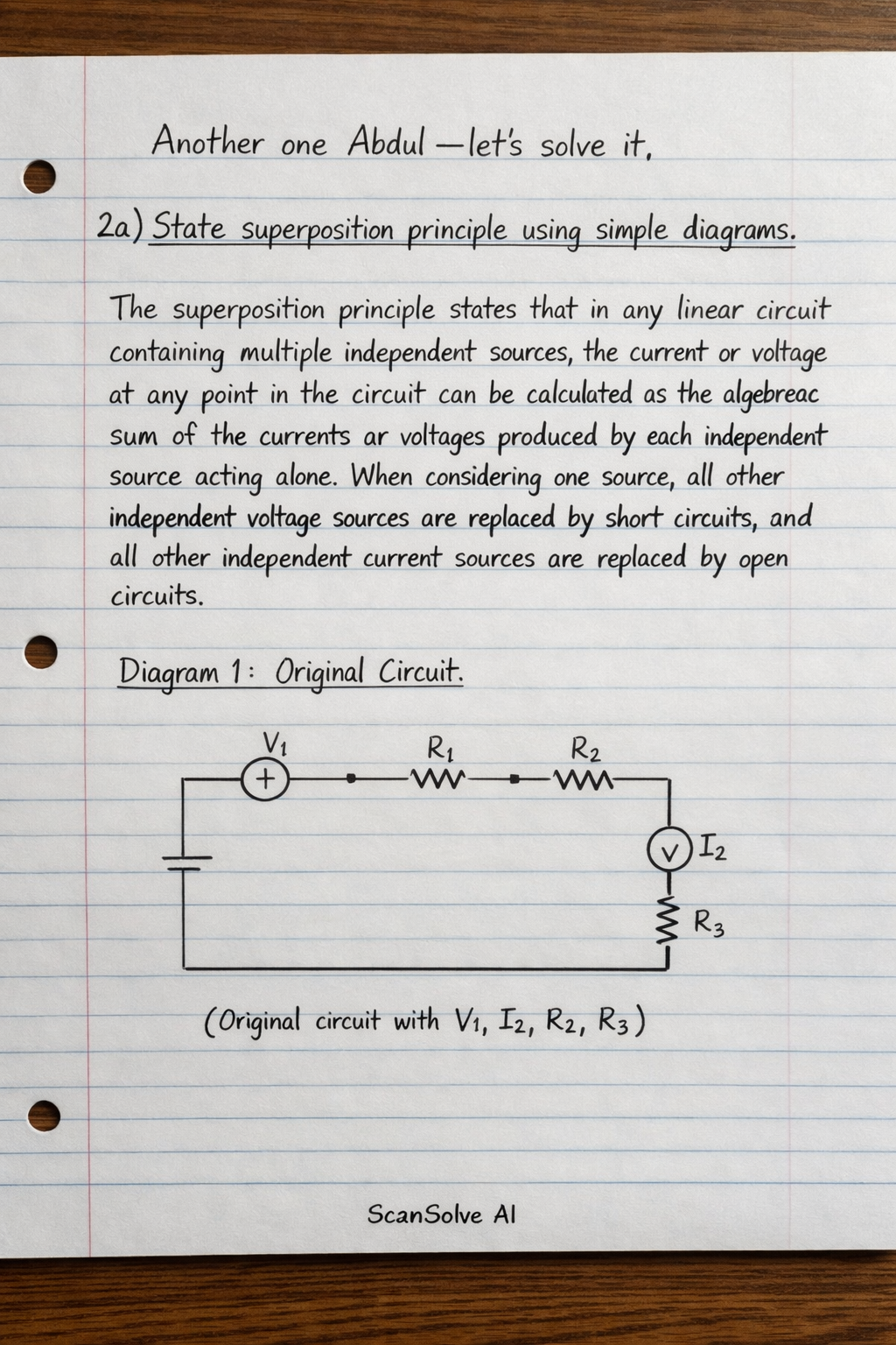
2a) State superposition principle using simple diagrams.
The superposition principle states that in any linear circuit containing multiple independent sources, the current or voltage at any point in the circuit can be calculated as the algebraic sum of the currents or voltages produced by each independent source acting alone. When considering one source, all other independent voltage sources are replaced by short circuits, and all other independent current sources are replaced by open circuits.
-
Diagram 1: Original Circuit
\begin{circuitikz} \draw (0,0) to[V,v_=$V_1$] (0,2) to[R=$R_1$] (2,2) to[R=$R_2$] (4,2) to[I,i_=$I_2$] (4,0) -- (0,0); \draw (2,2) -- (2,0) to[R=$R_3$] (4,0); \end{circuitikz}(Imagine a circuit with a voltage source and a current source , and resistors .) -
Diagram 2: acting alone ( open-circuited)
\begin{circuitikz} \draw (0,0) to[V,v_=$V_1$] (0,2) to[R=$R_1$] (2,2) to[R=$R_2$] (4,2); \draw (2,2) -- (2,0) to[R=$R_3$] (4,0) -- (0,0); \draw (4,2) -- (4,0); \end{circuitikz}(Imagine the same circuit, but the current source is replaced by an open circuit.) -
Diagram 3: acting alone ( short-circuited)
\begin{circuitikz} \draw (0,0) -- (0,2) to[R=$R_1$] (2,2) to[R=$R_2$] (4,2) to[I,i_=$I_2$] (4,0) -- (0,0); \draw (2,2) -- (2,0) to[R=$R_3$] (4,0); \end{circuitikz}(Imagine the same circuit, but the voltage source is replaced by a short circuit.)
2b) Use superposition theorem to calculate the current and power in the resistor in Fig. Q2a.
Step 1: Consider the 20V voltage source acting alone.
The 2A current source is open-circuited.
The and resistors are in parallel. Their equivalent resistance is:
This equivalent resistance is in series with the resistor. The total resistance seen by the 20V source is:
The total current from the 20V source is:
This current flows through the resistor. Now, use current division to find the current through the resistor:
The direction of is downwards.
Step 2: Consider the 2A current source acting alone.
The 20V voltage source is short-circuited.
The resistor is now in parallel with the resistor. Their equivalent resistance is:
The 2A current source splits between the resistor and the parallel combination .
The current flowing into the branch (which contains the resistor) is:
This then splits between the and resistors. The current through the resistor is:
The direction of is downwards.
Step 3: Calculate the total current and power in the resistor.
Since both currents and flow in the same (downwards) direction, they add up:
The power dissipated in the resistor is:
3a) For the network shown in Fig. Q2b, apply Norton's theorem to calculate the potential difference across the resistor.
Step 1: Remove the load resistor.
Let the terminals where the resistor was connected be A (top) and B (bottom).
Step 2: Calculate the Norton current () by short-circuiting terminals A and B.
When A and B are short-circuited, the resistor is in parallel with the short. Therefore, the voltage across the resistor is zero, and it effectively carries no current (or rather, the current takes the path of least resistance through the short).
The circuit simplifies to:
- Left branch: 8V source in series with .
- Right branch: 12V source in series with . Both branches are connected across the short circuit. Current from the left branch flowing into the short (from A to B): . Current from the right branch flowing into the short (from B to A): . The Norton current (from A to B) is the algebraic sum:
The negative sign indicates that the current flows from B to A. So, from B to A.
Step 3: Calculate the Norton resistance () by turning off independent sources.
- Replace the 8V voltage source with a short circuit.
- Replace the 12V voltage source with a short circuit. Looking into terminals A and B: The resistor is connected from A to ground. The resistor is connected from B to ground. The resistor is connected between A and B. This forms a parallel combination of the resistor with the series combination of the and resistors.
Step 4: Connect the load resistor () to the Norton equivalent circuit.
The Norton equivalent circuit consists of a current source (flowing from B to A) in parallel with . The load resistor is connected in parallel with this combination.
The current through the resistor () can be found using current division:
This current flows from B to A.
Step 5: Calculate the potential difference across the resistor.
Since the current flows from B to A, terminal B is at a higher potential than terminal A.
5a) Use simple diagram to explain Thevenin's theorem.
Thevenin's theorem states that any linear electrical network containing voltage sources, current sources, and resistors can be replaced by an equivalent circuit consisting of a single voltage source () in series with a single resistor () connected across the load terminals.
-
Diagram 1: Original Complex Circuit
\begin{circuitikz} \draw (0,0) to[V,v_=$V_s$] (0,2) to[R=$R_1$] (2,2) to[R=$R_2$] (2,0) -- (0,0); \draw (2,2) to[R=$R_3$] (4,2) node[right]{A}; \draw (2,0) to[R=$R_4$] (4,0) node[right]{B}; \draw (4,2) to[R=$R_L$] (4,0); \end{circuitikz}(Imagine a complex circuit with sources and resistors connected to a load resistor at terminals A and B.) -
Diagram 2: Thevenin Equivalent Circuit
\begin{circuitikz} \draw (0,0) to[V,v_=$V_{TH}$] (0,2) to[R=$R_{TH}$] (2,2) node[right]{A}; \draw (0,0) -- (2,0) node[right]{B}; \draw (2,2) to[R=$R_L$] (2,0); \end{circuitikz}(Imagine the complex circuit replaced by a voltage source in series with a resistor , connected to the same load resistor at terminals A and B.)
5b) For the network shown in Fig. Q3b, calculate the current in the resistor using Thevenin's theorem.
Assumption: The question refers to Fig. Q5b (as Q3b is already used) and the resistor is the load resistor () connected between the top-right and bottom-right terminals of the circuit.
Step 1: Remove the load resistor ().
Let the terminals be A (top-right, after ) and B (bottom-right, after ).
Step 2: Calculate Thevenin voltage ().
With terminals A and B open, no current flows through the and resistors.
The circuit consists of the 15A current source in parallel with the resistor, connected to the series combination of and .
The equivalent resistance of the series branch is .
The 15A current splits between the resistor and the series branch.
The current flowing through the branch () is:
The voltage across the resistor is .
The voltage at the node between and (let's call it ) relative to ground is .
The voltage at the node where the source, , and connect (let's call it ) is .
Since terminals A and B are open, is the voltage at the node before the resistor, and is the voltage at the node before the resistor.
So, and .
Step 3: Calculate Thevenin resistance () by turning off independent sources.
Replace the 15A current source with an open circuit.
Looking into terminals A and B:
The resistor is in series with the resistor. This combination is in parallel with the resistor.
This is in series with the and resistors.
Still stuck on this one?
Ask a follow-up, and the answer starts from this question.
More Physics Questions
Handwritten Step-by-Step Solution
Get this as a handwritten image on WhatsApp — like a tutor wrote it for you.
Try on WhatsApp