
We read your photo as:
Complete the truth table to show all the different combinations possible in the circuit in Figure 9. Indicate a "0" for an off position, and "1" for an on or closed position.
Computer Science
ScanSolve AI Answer
Step-by-step solution
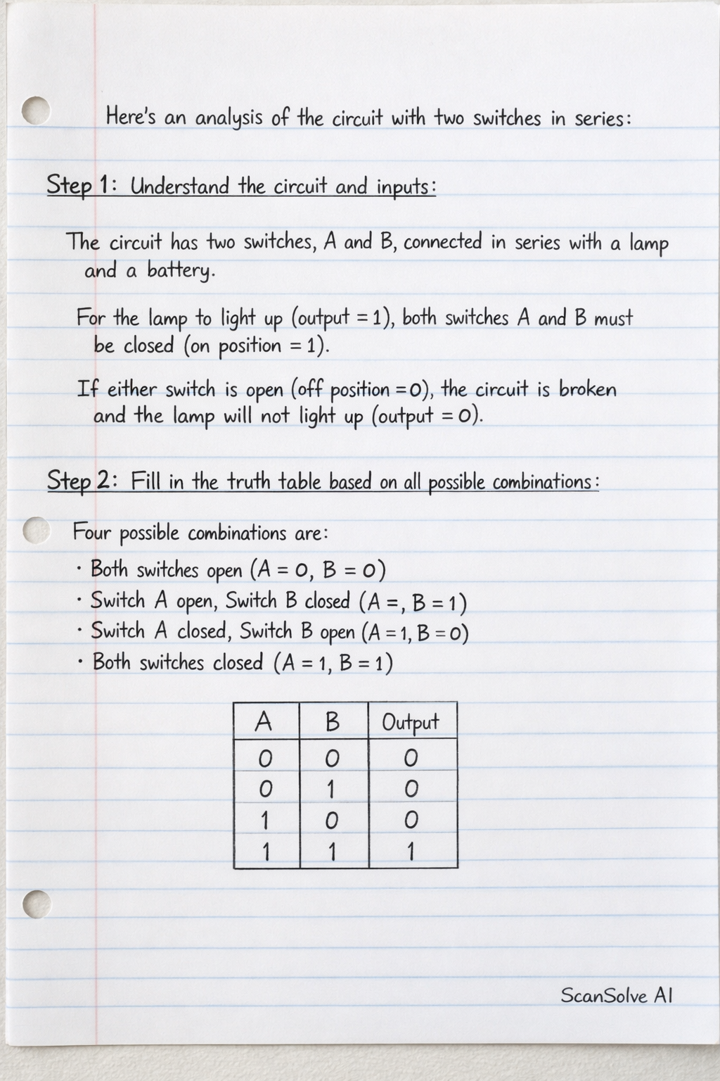
2 stepsHere is the completed truth table for the circuit with two switches in series:
Understand the circuit and inputs.
The circuit shows two switches, A and B, connected in series with a lamp and a battery. For the lamp to light up (output = 1), both switches A and B must be closed (on position = 1). If either switch is open (off position = 0), the circuit is broken, and the lamp will not light up (output = 0).
Fill in the truth table based on all possible combinations.
There are four possible combinations for two switches:
- Both switches open (A=0, B=0)
- Switch A open, Switch B closed (A=0, B=1)
- Switch A closed, Switch B open (A=1, B=0)
- Both switches closed (A=1, B=1)
Let's determine the output for each:
- If Input A = 0 and Input B = 0: Both switches are open, so the lamp is off. Output = 0.
- If Input A = 0 and Input B = 1: Switch A is open, so the lamp is off. Output = 0.
- If Input A = 1 and Input B = 0: Switch B is open, so the lamp is off. Output = 0.
- If Input A = 1 and Input B = 1: Both switches are closed, so the lamp is on. Output = 1.
Here is the completed truth table:
Was this helpful?
Still stuck on this one?
Ask a follow-up, and the answer starts from this question.
Got a different question?Ask your own question
More Computer Science Questions
QName the logic gate in figure 7 and draw its truth tableQComplete the truth table in Table 1 for the logic gate in Figure 1. (Based on the logic equation Z…QFig. 1 is a logic circuit, draw its truth table and derive its logic expression.QIn the figure 2.7, find I1, I2 and I3 of the switch as open and closed.QIdentify the circuit configuration when K is closed.
Handwritten Step-by-Step Solution
Get this as a handwritten image on WhatsApp — like a tutor wrote it for you.
Try on WhatsApp