
We read your photo as:
Draw the circuit diagram of your chosen scale model/prototype. Refer to Worksheet 34 (Informal)
Computer Science
ScanSolve AI Answer
As an AI, I cannot physically draw a diagram. However, I can describe the circuit diagram for your chosen scale model/prototype, which uses an LDR as an input and a buzzer as an output, powered by a 9V battery. This circuit will activate the buzzer when the LDR detects light.
Components:
- Battery (9V)
- Light Dependent Resistor (LDR)
- Fixed Resistor (e.g., 10 k)
- NPN Transistor (e.g., BC547)
- Buzzer
Circuit Description:
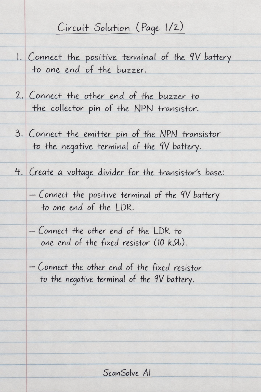
- Connect the positive terminal of the 9V battery to one end of the buzzer.
- Connect the other end of the buzzer to the collector pin of the NPN transistor.
- Connect the emitter pin of the NPN transistor to the negative terminal of the 9V battery.
- Create a voltage divider for the transistor's base:
- Connect the positive terminal of the 9V battery to one end of the LDR.
- Connect the other end of the LDR to one end of the fixed resistor (e.g., 10 k).
- Connect the other end of the fixed resistor to the negative terminal of the 9V battery.
- Connect the base pin of the NPN transistor to the junction between the LDR and the fixed resistor.
This setup allows the LDR to control the transistor, which in turn switches the buzzer on or off based on the light level.
Was this helpful?
Still stuck on this one?
Ask a follow-up, and the answer starts from this question.
Got a different question?Ask your own question
More Computer Science Questions
QDraw the circuit diagram.QI) Draw a circuit diagram for the arrangement.QDraw the symbol representing each component: 1.1 Cell 1.2 Battery 1.3 Resistor 1.4 Light bulb 1.5…QDraw the wiring diagram of the circuit. Install and wire the circuit for correct operation to…QDraw a wiring diagram for the bell circuit shown in Figure 2.
Handwritten Step-by-Step Solution
Get this as a handwritten image on WhatsApp — like a tutor wrote it for you.
Try on WhatsApp