
Using thevenin s theorem through direct formula clearly step by step please
ScanSolve AI Answer
Answer
Step-by-step solution
5 stepsOkay, let's re-evaluate the problem using Thevenin's theorem with a direct, step-by-step formula application. We are referring to the circuit diagram from the previous question (Q1b).
Goal: Determine the current, p.d., and power across the 10 load resistance using Thevenin's theorem.
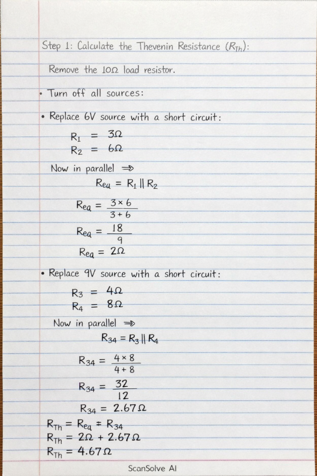
Calculate the Thevenin Resistance ().
To find , we first remove the load resistor (the 10 resistor between terminals A and B). Then, we turn off all independent voltage sources (replace them with short circuits) and independent current sources (replace them with open circuits).
- Replace the 6V voltage source with a short circuit. This connects node C directly to node D.
- Replace the 9V voltage source with a short circuit. This connects node F directly to node D.
Now, nodes C, D, and F are all electrically connected to the same point (let's call it ground for simplicity).
Looking into terminals A and B:- The 4 resistor is connected between terminal A and node C (which is now ground).
- The 6 resistor is connected between terminal B and node D (which is now ground).
- The 5 resistor is connected between node C and node F. Since C and F are both connected to D (ground), the 5 resistor is connected between two points that are at the same potential. This means the 5 resistor is shorted out and does not contribute to between A and B.
The effective path between A and B is through the 4 resistor to ground (C/D/F) and then from ground (C/D/F) through the 6 resistor to B. Therefore, the 4 and 6 resistors are in series when viewed from terminals A and B.
Calculate the Thevenin Voltage ().
To find , we determine the open-circuit voltage across the terminals where the load resistor was removed (terminals A and B). This is .
- With the 10 load removed, no current flows through the 4 resistor (connected to A) or the 6 resistor (connected to B) because the circuit is open at A-B.
- Let's set node D as the reference node ().
- The 6V source is connected between C and D, with C being positive. So, .
- The 9V source is connected between F and D, with F being positive. So, .
- The current flowing through the 5 resistor (between C and F) is : This means flows from F to C.
- Since no current flows through the 4 resistor, there is no voltage drop across it. Thus, the voltage at terminal A is the same as the voltage at node C:
- Since no current flows through the 6 resistor, there is no voltage drop across it. Thus, the voltage at terminal B is the same as the voltage at node D:
- The Thevenin voltage is the potential difference between A and B:
Connect the Thevenin equivalent circuit to the load and calculate the current ().
The Thevenin equivalent circuit consists of in series with . Now, reconnect the 10 load resistor () to this equivalent circuit.
The total resistance in the series circuit is .The current flowing through the load resistor is given by Ohm's Law:
The current across the 10 resistance is .
Calculate the potential difference (p.d.) across the load ().
Using Ohm's Law for the load resistor:
The p.d across the 10 resistance is .
Calculate the power consumed by the load ().
Using the formula for power:
The power consumed by the 10 resistance is .
Try one yourself
A new problem that tests the same skill.
Still stuck on this one?
Ask a follow-up, and the answer starts from this question.
More Mathematics Questions
Handwritten Step-by-Step Solution
Get this as a handwritten image on WhatsApp — like a tutor wrote it for you.
Try on WhatsApp