This physics problem tests your understanding of fundamental physical laws and their applications. The step-by-step solution below breaks down the problem using relevant equations and physical reasoning.
ScanSolve AI Answer
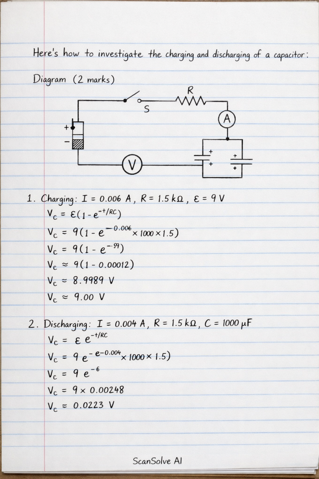
Here's how to investigate the charging and discharging of a capacitor: Diagram (2 marks) [ thick, battery/.pic= (0,0) -- (0,0.5); (0.2,0) -- (0.2,0.5); (0.1,0.5) -- (0.1,0.7); (0.1,0) -- (0.1,-0.2); at (0.1,0.8) +; at (0.1,-0.3) -; , resistor/.pic= (0,0) -- (0.2,0) -- (0.3,0.2) -- (0.5,-0.2) -- (0.7,0.2) -- (0.9,-0.2) -- (1,0) -- (1.2,0); , capacitor/.pic= (0,0) -- (0.2,0); (0.2,0) -- (0.2,0.5); (0.4,0) -- (0.4,0.5); (0.4,0) -- (0.6,0); at (0.3,0.25) +; at (0.3,0.25) -; , voltmeter/.pic= (0,0) circle (0.3); at (0,0) V; , ammeter/.pic= (0,0) circle (0.3); at (0,0) A; , switch/.pic= (0,0) -- (0.2,0); (0.2,0) circle (0.05); (0.5,0.3) circle (0.05); (0.2,0) -- (0.5,0.3); (0.5,0.3) -- (0.7,0.3); ] % Circuit components (BattP) at (0,3); (BattN) at (0,0); (SwitchA) at (1.5,3); (SwitchB) at (1.5,0); (SwitchC) at (1.5,1.5); % Common point of switch (Resistor1_start) at (3,1.5); (Resistor1_end) at (4.5,1.5); (Capacitor_start) at (4.5,0); (Capacitor_end) at (4.5,3); (Ammeter_pos) at (3,0); (Ammeter_neg) at (3,3); % Connections (BattP) -- (SwitchA); (BattN) -- (SwitchB); (SwitchC) -- (Resistor1_start); (Resistor1_end) -- (Capacitor_end); (Capacitor_start) -- (BattN); % Connects capacitor to ground/negative terminal (Resistor1_start) -- (Ammeter_neg); % Ammeter in series (Ammeter_pos) -- (SwitchC); % Ammeter in series % Components at (0.5,1.5) battery; at (0.5, 2.5) E; % EMF at (3.75,1.5) resistor; at (3.75, 2) R; at (4.5,0.75) capacitor; at (5, 0.75) C; at (2.25,1.5) ammeter; at (2.25, 2) A; % Voltmeter across capacitor at (5.5,1.5) voltmeter; (4.5,3) -- (5.5,1.5); (4.5,0) -- (5.5,1.5); at (6, 1.5) V; % Switch (SPDT) (1.5,0) -- (1.5,3); % Switch rail [fill=black] (1.5,1.5) circle (0.08); % Pivot [thick] (1.5,1.5) -- (1.5,3); % Charging position at (1.2, 3) 1 (Charge); at (1.2, 0) 2 (Discharge); at (1.2, 1.5) Common; Method/Precaution (4 marks) Method: 1. Set up the circuit as shown, connecting a DC power supply (E), a resistor (R), and a capacitor (C) with a double-pole, double-throw (DPDT) switch (or two single-pole switches). Connect a voltmeter (V) in parallel across the capacitor and an ammeter (A) in series with the resistor and capacitor. 2. Charging: Move the switch to position 1 to connect the capacitor to the power supply through the resistor. Start a stopwatch simultaneously. Record the voltmeter reading (voltage across the capacitor) and the ammeter reading (current through the circuit) at regular time intervals (e.g., every 5 seconds) until the capacitor is fully charged (voltmeter reading equals supply voltage, ammeter reading is zero). 3. Discharging: Once the capacitor is fully charged, immediately move the switch to position 2 to disconnect the power supply and connect the capacitor directly across the resistor. Start the stopwatch again (or reset and restart). Record the voltmeter and ammeter readings at regular time intervals until the capacitor is fully discharged (both readings are zero). 4. Plot graphs of voltage versus time (V_C vs t) and current versus time (I vs t) for both charging and discharging. Precaution: Ensure the correct polarity* for electrolytic capacitors to prevent damage. Use a high-resistance voltmeter* to ensure it draws negligible current from the circuit, thus not affecting the charging/discharging process. Ensure all connections are tight* to minimize contact resistance, which could alter the effective resistance of the circuit and the time constant. Observation (2 marks) Charging: The voltmeter reading across the capacitor increases exponentially from zero to the supply voltage. The ammeter reading decreases exponentially* from a maximum value to zero. Discharging: The voltmeter reading across the capacitor decreases exponentially from the supply voltage to zero. The ammeter reading decreases exponentially* from a maximum value (in the opposite direction) to zero. Inference/Conclusion (2 marks) The charging and discharging of a capacitor through a resistor are exponential processes. During charging, the capacitor stores electrical energy, and its voltage rises as current flows into it. During discharging, the capacitor releases its stored energy through the resistor, and its voltage falls as current flows out of it. The rate of charging and discharging is determined by the time constant ( = RC), which is the product of the resistance and capacitance in the circuit. 3 done, 2 left today. You're making progress.