We read your photo as:

Determine: i. the equivalent resistance. ii. the supply current. iii. the current flowing in each resistor. (d) Differentiate between voltage divider and current divider with the aid of diagram.

Physics

ScanSolve AI Answer

Step-by-step solution

24 steps

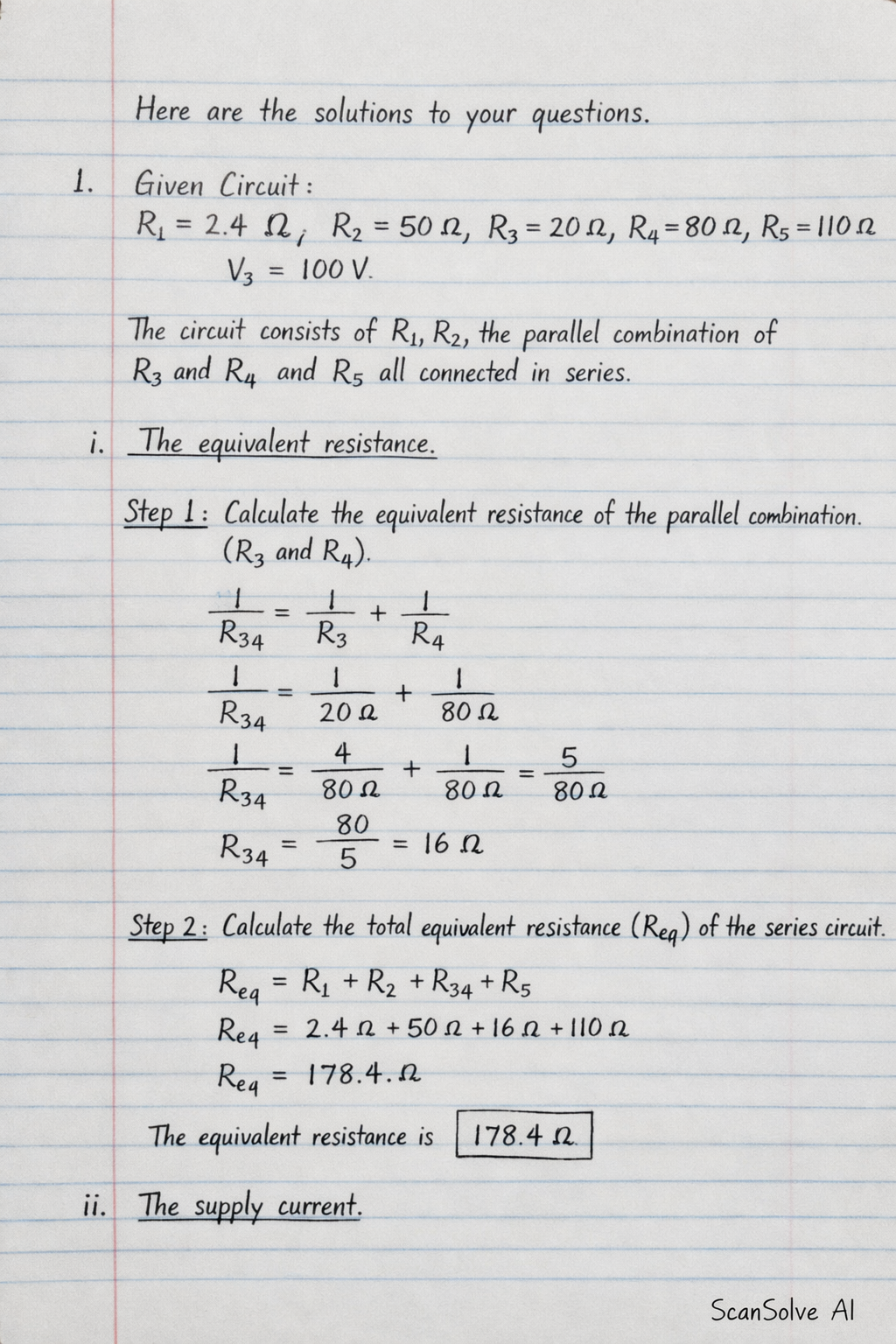
Here are the solutions to your questions.

1.

  • Given Circuit:
    • Resistors: R1=2.4 ΩR_1 = 2.4\, \Omega, R2=50 ΩR_2 = 50\, \Omega, R3=20 ΩR_3 = 20\, \Omega, R4=80 ΩR_4 = 80\, \Omega, R5=110 ΩR_5 = 110\, \Omega
    • Supply Voltage: VS=100 VV_S = 100\, \text{V}

The circuit consists of R1R_1, R2R_2, the parallel combination of R3R_3 and R4R_4, and R5R_5 all connected in series.

i. The equivalent resistance.

  1. Calculate the equivalent resistance of the parallel combination (R3R_3 and R4R_4).

    1R34=1R3+1R4\frac{1}{R_{34}} = \frac{1}{R_3} + \frac{1}{R_4} 1R34=120 Ω+180 Ω\frac{1}{R_{34}} = \frac{1}{20\, \Omega} + \frac{1}{80\, \Omega} 1R34=480 Ω+180 Ω=580 Ω\frac{1}{R_{34}} = \frac{4}{80\, \Omega} + \frac{1}{80\, \Omega} = \frac{5}{80\, \Omega} R34=805 Ω=16 ΩR_{34} = \frac{80}{5}\, \Omega = 16\, \Omega
  2. Calculate the total equivalent resistance (ReqR_{eq}) of the series circuit.

    Req=R1+R2+R34+R5R_{eq} = R_1 + R_2 + R_{34} + R_5 Req=2.4 Ω+50 Ω+16 Ω+110 ΩR_{eq} = 2.4\, \Omega + 50\, \Omega + 16\, \Omega + 110\, \Omega Req=178.4 ΩR_{eq} = 178.4\, \Omega

    The equivalent resistance is 178.4 Ω\boxed{\text{178.4 } \Omega}.

    ii. The supply current.

  3. Use Ohm's Law to find the total supply current (ISI_S).

    IS=VSReqI_S = \frac{V_S}{R_{eq}} IS=100 V178.4 ΩI_S = \frac{100\, \text{V}}{178.4\, \Omega} IS≈0.5605 AI_S \approx 0.5605\, \text{A}

    The supply current is 0.5605 A\boxed{\text{0.5605 A}}.

    iii. The current flowing in each resistor.

  4. Determine currents for series resistors.

    Since R1R_1, R2R_2, and R5R_5 are in series with the voltage source, the current flowing through them is the total supply current.

    I1=I2=I5=IS≈0.5605 AI_1 = I_2 = I_5 = I_S \approx 0.5605\, \text{A}
  5. Determine voltage across the parallel combination.

    The voltage across the parallel combination (R34R_{34}) is V34=IS×R34V_{34} = I_S \times R_{34}.

    V34=0.5605 A×16 ΩV_{34} = 0.5605\, \text{A} \times 16\, \Omega V34≈8.968 VV_{34} \approx 8.968\, \text{V}
  6. Determine currents for parallel resistors.

    The current through R3R_3 is I3=V34R3I_3 = \frac{V_{34}}{R_3}.

    I3=8.968 V20 Ω≈0.4484 AI_3 = \frac{8.968\, \text{V}}{20\, \Omega} \approx 0.4484\, \text{A}

    The current through R4R_4 is I4=V34R4I_4 = \frac{V_{34}}{R_4}.

    I4=8.968 V80 Ω≈0.1121 AI_4 = \frac{8.968\, \text{V}}{80\, \Omega} \approx 0.1121\, \text{A}

    The currents flowing in each resistor are:
    I1=0.5605 AI_1 = \boxed{\text{0.5605 A}}
    I2=0.5605 AI_2 = \boxed{\text{0.5605 A}}
    I3=0.4484 AI_3 = \boxed{\text{0.4484 A}}
    I4=0.1121 AI_4 = \boxed{\text{0.1121 A}}
    I5=0.5605 AI_5 = \boxed{\text{0.5605 A}}

    iv. Differentiate between voltage divider and current divider with the aid of diagram.

    • Voltage Divider: A circuit configuration, typically a series connection of resistors, used to produce an output voltage that is a fraction of its input voltage. The voltage across each resistor is proportional to its resistance.
      • Diagram (conceptual): Two resistors R1R_1 and R2R_2 connected in series to a voltage source VinV_{in}. The output voltage VoutV_{out} is measured across R2R_2.
      • Formula: Vout=VinR2R1+R2V_{out} = V_{in} \frac{R_2}{R_1 + R_2}
    • Current Divider: A circuit configuration, typically a parallel connection of resistors, used to split the input current into multiple branches. The current through each branch is inversely proportional to its resistance.
      • Diagram (conceptual): Two resistors R1R_1 and R2R_2 connected in parallel to a current source IinI_{in}. The current I2I_2 through R2R_2 is a fraction of IinI_{in}.
      • Formula: I2=IinR1R1+R2I_2 = I_{in} \frac{R_1}{R_1 + R_2}

    2. (a) Parallel Resistors:

    • Given:
      • Resistors: R1=10 ΩR_1 = 10\, \Omega, R2=20 ΩR_2 = 20\, \Omega, R3=30 ΩR_3 = 30\, \Omega (connected in parallel)
      • Supply Voltage: VS=240 VV_S = 240\, \text{V}

    i. The equivalent resistance.

  7. Calculate the equivalent resistance (ReqR_{eq}) for parallel resistors.

    1Req=1R1+1R2+1R3\frac{1}{R_{eq}} = \frac{1}{R_1} + \frac{1}{R_2} + \frac{1}{R_3} 1Req=110 Ω+120 Ω+130 Ω\frac{1}{R_{eq}} = \frac{1}{10\, \Omega} + \frac{1}{20\, \Omega} + \frac{1}{30\, \Omega} 1Req=660 Ω+360 Ω+260 Ω=1160 Ω\frac{1}{R_{eq}} = \frac{6}{60\, \Omega} + \frac{3}{60\, \Omega} + \frac{2}{60\, \Omega} = \frac{11}{60\, \Omega} Req=6011 Ω≈5.4545 ΩR_{eq} = \frac{60}{11}\, \Omega \approx 5.4545\, \Omega

    The equivalent resistance is 5.4545 Ω\boxed{\text{5.4545 } \Omega}.

    ii. The current flowing through the circuit.

  8. Use Ohm's Law to find the total supply current (ISI_S).

    IS=VSReqI_S = \frac{V_S}{R_{eq}} IS=240 V60/11 Ω=240×1160 AI_S = \frac{240\, \text{V}}{60/11\, \Omega} = \frac{240 \times 11}{60}\, \text{A} IS=4×11 A=44 AI_S = 4 \times 11\, \text{A} = 44\, \text{A}

    The current flowing through the circuit is 44 A\boxed{\text{44 A}}.

    iii. The current passing through each resistor.

  9. Apply Ohm's Law to each resistor.

    In a parallel circuit, the voltage across each resistor is equal to the supply voltage (VS=240 VV_S = 240\, \text{V}).
    Current through R1R_1:

    I1=VSR1=240 V10 Ω=24 AI_1 = \frac{V_S}{R_1} = \frac{240\, \text{V}}{10\, \Omega} = 24\, \text{A}

    Current through R2R_2:

    I2=VSR2=240 V20 Ω=12 AI_2 = \frac{V_S}{R_2} = \frac{240\, \text{V}}{20\, \Omega} = 12\, \text{A}

    Current through R3R_3:

    I3=VSR3=240 V30 Ω=8 AI_3 = \frac{V_S}{R_3} = \frac{240\, \text{V}}{30\, \Omega} = 8\, \text{A}

    The currents passing through each resistor are:
    I1=24 AI_1 = \boxed{\text{24 A}}
    I2=12 AI_2 = \boxed{\text{12 A}}
    I3=8 AI_3 = \boxed{\text{8 A}}

    iv. Power dissipated by the 30 Ω30\, \Omega resistor.

  10. Calculate power using P=V2/RP = V^2/R.

    For the 30 Ω30\, \Omega resistor (R3R_3), the voltage across it is VS=240 VV_S = 240\, \text{V}.

    P3=VS2R3P_3 = \frac{V_S^2}{R_3} P3=(240 V)230 Ω=57600 V230 ΩP_3 = \frac{(240\, \text{V})^2}{30\, \Omega} = \frac{57600\, \text{V}^2}{30\, \Omega} P3=1920 WP_3 = 1920\, \text{W}

    The power dissipated by the 30 Ω30\, \Omega resistor is 1920 W\boxed{\text{1920 W}}.

    2. (b) Household Lighting:

    • Given:
      • Number of lights: 22
      • Power per light: 100 W100\, \text{W}
      • Operating time: 8 hours/day
      • Supply Voltage: 220 V220\, \text{V}
      • Cost of electricity: Ksh 14.35 per kWh

    i. Calculate the total current when all the lights are in operation.

  11. Calculate the total power of all lights.

    Ptotal=22×100 W=2200 WP_{total} = 22 \times 100\, \text{W} = 2200\, \text{W}
  12. Calculate the total current using P=VIP = VI.

    Itotal=PtotalVI_{total} = \frac{P_{total}}{V} Itotal=2200 W220 VI_{total} = \frac{2200\, \text{W}}{220\, \text{V}} Itotal=10 AI_{total} = 10\, \text{A}

    The total current is 10 A\boxed{\text{10 A}}.

    ii. Determine the annual lighting bill for the house if 1kWh of electricity costs Ksh 14.35.

  13. Calculate the energy consumed per day.

    Eday=Ptotal×time per dayE_{day} = P_{total} \times \text{time per day} Eday=2200 W×8 h=17600 WhE_{day} = 2200\, \text{W} \times 8\, \text{h} = 17600\, \text{Wh}

    Convert to kWh:

    Eday=176001000 kWh=17.6 kWhE_{day} = \frac{17600}{1000}\, \text{kWh} = 17.6\, \text{kWh}
  14. Calculate the energy consumed per year.

    Eyear=Eday×365 days/yearE_{year} = E_{day} \times 365\, \text{days/year} Eyear=17.6 kWh/day×365 days=6424 kWhE_{year} = 17.6\, \text{kWh/day} \times 365\, \text{days} = 6424\, \text{kWh}
  15. Calculate the annual lighting bill.

    Annual Bill=Eyear×Cost per kWh\text{Annual Bill} = E_{year} \times \text{Cost per kWh} Annual Bill=6424 kWh×Ksh 14.35/kWh\text{Annual Bill} = 6424\, \text{kWh} \times \text{Ksh 14.35/kWh} Annual Bill=Ksh 92103.40\text{Annual Bill} = \text{Ksh 92103.40}

    The annual lighting bill is Ksh 92103.40\boxed{\text{Ksh 92103.40}}.

    3. (a) Series Capacitors:

    • Given:
      • Capacitors: C1=6 μFC_1 = 6\, \mu\text{F}, C2=12 μFC_2 = 12\, \mu\text{F} (connected in series)
      • Supply Voltage: VS=120 VV_S = 120\, \text{V}
  16. Calculate the equivalent capacitance (CeqC_{eq}) for capacitors in series.

    1Ceq=1C1+1C2\frac{1}{C_{eq}} = \frac{1}{C_1} + \frac{1}{C_2} 1Ceq=16 μF+112 μF\frac{1}{C_{eq}} = \frac{1}{6\, \mu\text{F}} + \frac{1}{12\, \mu\text{F}} 1Ceq=212 μF+112 μF=312 μF=14 μF\frac{1}{C_{eq}} = \frac{2}{12\, \mu\text{F}} + \frac{1}{12\, \mu\text{F}} = \frac{3}{12\, \mu\text{F}} = \frac{1}{4\, \mu\text{F}} Ceq=4 μFC_{eq} = 4\, \mu\text{F}
  17. Calculate the total charge (QtotalQ_{total}).

    In a series capacitor circuit, the charge on each capacitor is the same and equal to the total charge.

    Qtotal=Ceq×VSQ_{total} = C_{eq} \times V_S Qtotal=(4×10⁻⁶ F)×120 V=480×10−6 C=480 μCQ_{total} = (4 \times 10^{-6}\, \text{F}) \times 120\, \text{V} = 480 \times 10^{-6}\, \text{C} = 480\, \mu\text{C}

    So, the charge on each capacitor is:
    Q1=480 μCQ_1 = \boxed{\text{480 } \mu\text{C}}
    Q2=480 μCQ_2 = \boxed{\text{480 } \mu\text{C}}

  18. Calculate the voltage across each capacitor.

    V1=Q1C1=480 μC6 μF=80 VV_1 = \frac{Q_1}{C_1} = \frac{480\, \mu\text{C}}{6\, \mu\text{F}} = 80\, \text{V} V2=Q2C2=480 μC12 μF=40 VV_2 = \frac{Q_2}{C_2} = \frac{480\, \mu\text{C}}{12\, \mu\text{F}} = 40\, \text{V}

    The voltage across each capacitor is:
    V1=80 VV_1 = \boxed{\text{80 V}}
    V2=40 VV_2 = \boxed{\text{40 V}}

  19. Calculate the energy stored in each capacitor.

    E=12CV2E = \frac{1}{2} C V^2

    For C1C_1:

    E1=12(6×10⁻⁶ F)(80 V)2=12×6×10−6×6400 JE_1 = \frac{1}{2} (6 \times 10^{-6}\, \text{F}) (80\, \text{V})^2 = \frac{1}{2} \times 6 \times 10^{-6} \times 6400\, \text{J} E1=19200×10−6 J=0.0192 JE_1 = 19200 \times 10^{-6}\, \text{J} = 0.0192\, \text{J}

    For C2C_2:

    E2=12(12×10−6 F)(40 V)2=12×12×10−6×1600 JE_2 = \frac{1}{2} (12 \times 10^{-6}\, \text{F}) (40\, \text{V})^2 = \frac{1}{2} \times 12 \times 10^{-6} \times 1600\, \text{J} E2=9600×10−6 J=0.0096 JE_2 = 9600 \times 10^{-6}\, \text{J} = 0.0096\, \text{J}

    The energy stored in each capacitor is:
    E1=0.0192 JE_1 = \boxed{\text{0.0192 J}}
    E2=0.0096 JE_2 = \boxed{\text{0.0096 J}}

    3. (b) RC Circuit (Charging Capacitor):

    • Given:
      • Capacitor: C=10 μF=10×10−6 FC = 10\, \mu\text{F} = 10 \times 10^{-6}\, \text{F}
      • Resistor: R=1 kΩ=1×10³ ΩR = 1\, \text{k}\Omega = 1 \times 10^3\, \Omega
      • Supply Voltage: VS=100 VV_S = 100\, \text{V}

    i. The time constant.

  20. Calculate the time constant (τ\tau).

    τ=RC\tau = RC τ=(1×10³ Ω)×(10×10−6 F)\tau = (1 \times 10^3\, \Omega) \times (10 \times 10^{-6}\, \text{F}) τ=10×10−3 s=0.01 s\tau = 10 \times 10^{-3}\, \text{s} = 0.01\, \text{s}

    The time constant is 0.01 s\boxed{\text{0.01 s}}.

    ii. The initial charging current.

  21. Calculate the initial current (I0I_0).

    At the instant the switch is closed (t=0t=0), the capacitor acts as a short circuit, so the current is limited only by the resistor.

    I0=VSRI_0 = \frac{V_S}{R} I0=100 V1×103 ΩI_0 = \frac{100\, \text{V}}{1 \times 10^3\, \Omega} I0=0.1 AI_0 = 0.1\, \text{A}

    The initial charging current is 0.1 A\boxed{\text{0.1 A}}.

    iii. The voltage on the capacitor after 10 ms10\, \text{ms}.

  22. Use the charging capacitor voltage formula.

    The voltage across a charging capacitor is given by VC(t)=VS(1−e−t/τ)V_C(t) = V_S (1 - e^{-t/\tau}).
    Given t=10 ms=0.01 st = 10\, \text{ms} = 0.01\, \text{s} and τ=0.01 s\tau = 0.01\, \text{s}.

    VC(0.01 s)=100 V(1−e−0.01 s/0.01 s)V_C(0.01\, \text{s}) = 100\, \text{V} (1 - e^{-0.01\, \text{s}/0.01\, \text{s}}) VC(0.01 s)=100 V(1−e−1)V_C(0.01\, \text{s}) = 100\, \text{V} (1 - e^{-1}) VC(0.01 s)=100 V(1−0.36788)V_C(0.01\, \text{s}) = 100\, \text{V} (1 - 0.36788) VC(0.01 s)=100 V(0.63212)V_C(0.01\, \text{s}) = 100\, \text{V} (0.63212) VC(0.01 s)≈63.21 VV_C(0.01\, \text{s}) \approx 63.21\, \text{V}

    The voltage on the capacitor after 10 ms10\, \text{ms} is 63.21 V\boxed{\text{63.21 V}}.

    iv. The time taken for the capacitor to charge to 90% of its final value.

  23. Set up the equation for 90% of the final voltage.

    The final voltage is VS=100 VV_S = 100\, \text{V}. So, 90% of the final value is 0.9×100 V=90 V0.9 \times 100\, \text{V} = 90\, \text{V}.

    VC(t)=VS(1−e−t/τ)V_C(t) = V_S (1 - e^{-t/\tau}) 90 V=100 V(1−e−t/τ)90\, \text{V} = 100\, \text{V} (1 - e^{-t/\tau})
  24. Solve for tt.

    0.9=1−e−t/τ0.9 = 1 - e^{-t/\tau} e−t/τ=1−0.9e^{-t/\tau} = 1 - 0.9 e−t/τ=0.1e^{-t/\tau} = 0.1

    Take the natural logarithm of both sides:

    −t/τ=ln⁡(0.1)-t/\tau = \ln(0.1) −t/τ≈−2.302585-t/\tau \approx -2.302585 t=τ×2.302585t = \tau \times 2.302585

    Using τ=0.01 s\tau = 0.01\, \text{s}:

    t=0.01 s×2.302585t = 0.01\, \text{s} \times 2.302585 t≈0.023026 st \approx 0.023026\, \text{s}

    The time taken is 0.023026 s\boxed{\text{0.023026 s}}.

    2 zimekamilika. Zimebaki 3 leo — tuma inayofuata.

Was this helpful?

Still stuck on this one?

Ask a follow-up, and the answer starts from this question.

Got a different question?Ask your own question
Handwritten step-by-step solution preview

Handwritten Step-by-Step Solution

Get this as a handwritten image on WhatsApp — like a tutor wrote it for you.

Try on WhatsApp