
We read your photo as:
Find Io, I1, I2 when (a) Switch is closed for balanced load (b) Switch is open.
Physics
ScanSolve AI Answer
Step-by-step solution
5 stepsHere's how to solve this circuit problem:
The diagram shows a three-phase system with three input currents, each . The triangular shape represents a three-phase load, most likely a delta connection, given the direct connections to the vertices. The currents , , and are shown leaving the vertices. In a standard three-phase delta connection, these would typically represent the phase currents flowing within the branches of the delta. We will assume refer to the magnitudes of these phase currents.
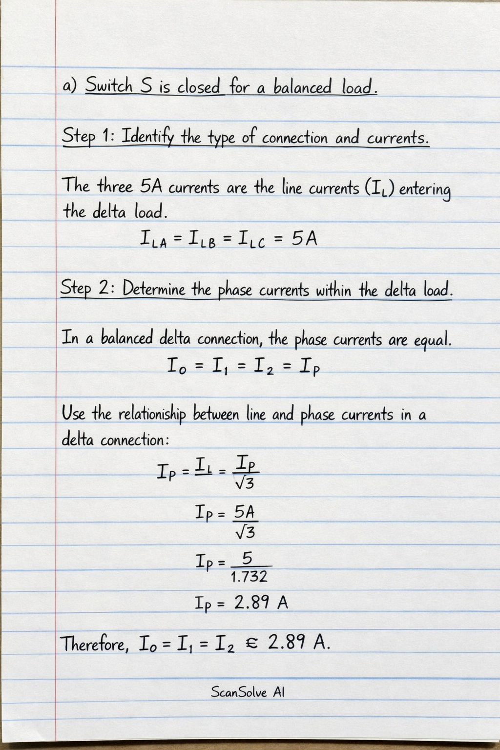
- a) Switch S is closed for a balanced load.
Identify the type of connection and currents.
The three $5A$ currents are the line currents ($I_L$) entering a balanced three-phase delta-connected load. The currents $I_0, I_1, I_2$ are the phase currents ($I_P$) within the delta load.Apply the relationship between line and phase currents for a balanced delta load.
For a balanced delta-connected load, the magnitude of the line current is $\sqrt{3}$ times the magnitude of the phase current: $$ I_L = \sqrt{3} I_P $$ Therefore, the phase current is: $$ I_P = \frac{I_L}{\sqrt{3}} $$Substitute the given line current and calculate the phase currents.
Given $I_L = 5A$: $$ I_0 = I_1 = I_2 = \frac{5}{\sqrt{3}} \text{ A} $$ $$ I_0 = I_1 = I_2 \approx \frac{5}{1.732} \text{ A} $$ $$ I_0 = I_1 = I_2 \approx 2.887 \text{ A} $$ The currents are: $$ \boxed{I_0 = I_1 = I_2 = \frac{5}{\sqrt{3}} \text{ A}} $$- b) Switch S is open.
Analyze the circuit configuration when the switch is open.
When switch S is open, the third input line (the bottom one) is disconnected from the load. This means the current in that line becomes $0A$. The system is no longer a balanced three-phase system; it becomes an open-delta (or V-connection) system.Determine the currents in the remaining phases.
In an open-delta system, the two remaining line currents are equal to the phase currents in the two active phases. The third phase current (corresponding to the disconnected line) will be zero.
From the diagram, the top input line (corresponding to $I_0$) and the middle input line (corresponding to $I_1$) are still connected, each carrying $5A$. The bottom input line (corresponding to $I_2$) is disconnected.
Therefore, the phase currents will be:
$$
I_0 = 5 \text{ A}
$$
$$
I_1 = 5 \text{ A}
$$
$$
I_2 = 0 \text{ A}
$$
The currents are:
$$
\boxed{I_0 = 5 \text{ A}, I_1 = 5 \text{ A}, I_2 = 0 \text{ A}}
$$
Was this helpful?
Still stuck on this one?
Ask a follow-up, and the answer starts from this question.
Got a different question?Ask your own question
More Physics Questions
QIn the figure 2.7, find I1, I2 and I3 of the switch as open and closed.QWhen switch S is open, no current flows through the circuit (I=0).QThe switch in figure 1 has been closed for a long time. At t=0, the switch is opened. How would you…QA) Calculate the effective resistance of bulbs A and B. b) Switch S is now closed for a short time…QA. A.d.c. circuit comprises three closed loops. Applying Kirchhoff's laws to the closed loops gives…
Handwritten Step-by-Step Solution
Get this as a handwritten image on WhatsApp — like a tutor wrote it for you.
Try on WhatsApp