
We read your photo as:
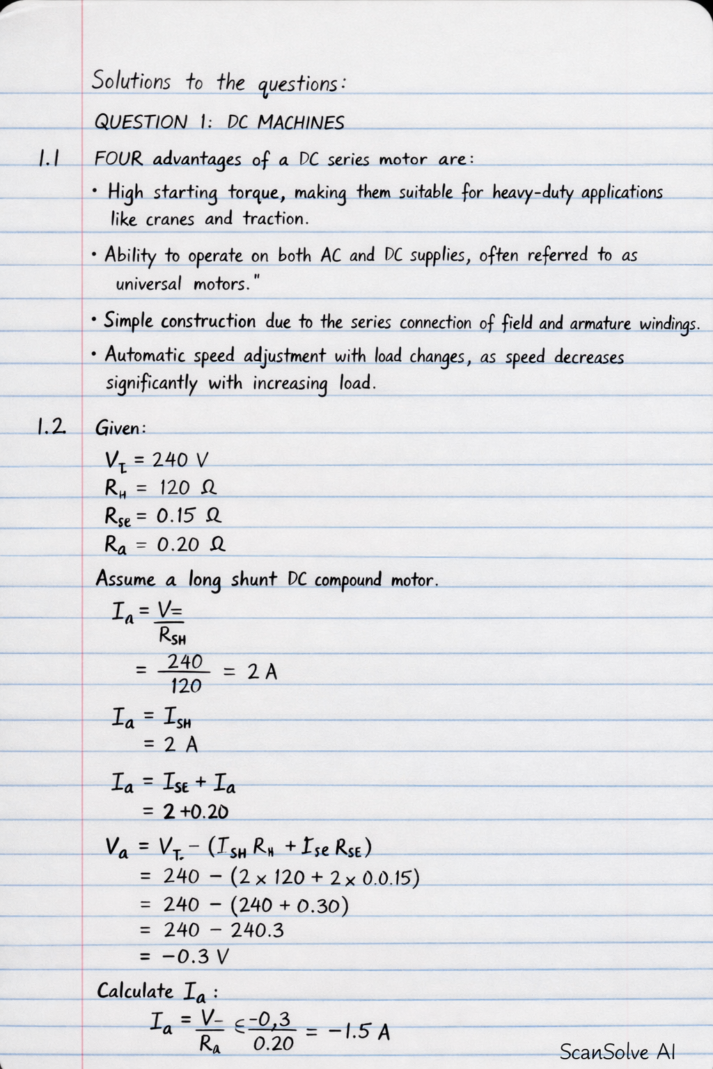
List FOUR advantages of a DC series motor.
ScanSolve AI Answer
Step-by-step solution
17 stepsHere are the solutions to the questions:
QUESTION 1: DC MACHINES
1.1 FOUR advantages of a DC series motor are:
- High starting torque, making them suitable for heavy-duty applications like cranes and traction.
- Ability to operate on both AC and DC supplies, often referred to as universal motors.
- Simple construction due to the series connection of field and armature windings.
- Automatic speed adjustment with load changes, as speed decreases significantly with increasing load.
1.2 Given: , , , .
Assume a long shunt DC compound motor.
1.2.1 The back EMF at no load
No-load: .
Calculate the shunt field current.
Calculate the armature current.
Calculate the back EMF at no load.
1.2.2 The torque developed at full load
Full-load: , .Calculate the shunt field current (assumed constant).
Calculate the armature current.
Calculate the back EMF at full load.
Calculate the power developed in the armature.
Calculate the angular speed.
Calculate the torque developed.
1.2.3 The shaft power at full load
Assuming rotational losses are negligible or not provided, the shaft power is approximately equal to the mechanical power developed in the armature.1.3 A DC generator with a differential compound winding has its series field winding connected such that its magnetic flux opposes the magnetic flux of the shunt field winding. This connection results in a decreasing terminal voltage with increasing load.
\begin{tikzpicture}[scale=0.8]
    % Armature
    \draw[thick] (0,0) circle (1.5cm);
    \node at (0,0) {Armature};
    \draw[thick] (0,1.5) -- (0,2);
    \draw[thick] (0,-1.5) -- (0,-2);

    % Brushes
    \draw[fill=black] (-0.5,1.5) rectangle (0.5,1.7);
    \draw[fill=black] (-0.5,-1.5) rectangle (0.5,-1.7);

    % Shunt Field
    \draw[thick] (0,2) -- (2,2) -- (2,0.5);
    \draw[thick] (0,-2) -- (2,-2) -- (2,-0.5);
    \draw[thick, decorate, decoration={coil,aspect=0.3,segment length=3mm,amplitude=2mm}] (2,0.5) -- (2,-0.5) node[right, midway] {$R_{sh}$};

    % Series Field
    \draw[thick] (0,2) -- (-2,2) -- (-2,0.5);
    \draw[thick] (0,-2) -- (-2,-2) -- (-2,-0.5);
    \draw[thick, decorate, decoration={coil,aspect=0.3,segment length=3mm,amplitude=2mm}] (-2,0.5) -- (-2,-0.5) node[left, midway] {$R_{se}$};

    % Load
    \draw[thick] (2,2) -- (3,2) node[right] {$V_T$};
    \draw[thick] (2,-2) -- (3,-2);
    \draw[thick] (3,2) -- (3,-2);
    \draw[thick] (3.5,0) node[right] {Load};

    % Arrows for current direction (indicating differential connection)
    \draw[->] (2,1.5) -- (2,0.5); % Shunt current down
    \draw[->] (-2,1.5) -- (-2,0.5); % Series current down (opposing shunt)
    \draw[->] (0,1.7) -- (0,2); % Armature current out
    \draw[->] (0,-1.7) -- (0,-2); % Armature current out
    \draw[->] (2.5,2) -- (3,2); % Load current
    \draw[->] (2.5,-2) -- (3,-2); % Load current
\end{tikzpicture}
Note: The diagram shows a long shunt connection, where the series field is in series with the armature, and this combination is in parallel with the shunt field and the load. For differential compounding, the winding direction of the series field is such that its magnetic field opposes the shunt field.
1.4 If the armature voltage of a DC shunt motor is increased while the load torque remains constant and the field flux is constant, the speed of the motor will increase. This is because with constant load torque and constant field flux, the armature current remains constant. An increase in armature voltage leads to an increase in the back EMF (), and since is proportional to speed (for constant flux), the speed must increase.
QUESTION 2: AC CIRCUIT THEORY
Given: Delta-connected load, per phase, , .
2.1 The line current
For a delta connection, the phase voltage is equal to the line voltage.
Calculate the magnitude of the phase impedance.
Calculate the phase current.
Calculate the line current for a delta connection.
2.2 The power factor
Calculate the power factor.
Since the impedance has a negative imaginary part (capacitive reactance), the power factor is leading.
2.3 The active power consumed
Calculate the active power.
2.4 The reactive power consumed
Calculate the reactive power.
The negative sign indicates that the load is supplying reactive power (or consuming negative reactive power), which is characteristic of a capacitive load.
2.5 The apparent power (kVA)
Calculate the apparent power.
Alternatively, using and :
Still stuck on this one?
Ask a follow-up, and the answer starts from this question.
More Physics Questions
Handwritten Step-by-Step Solution
Get this as a handwritten image on WhatsApp — like a tutor wrote it for you.
Try on WhatsApp