

This physics problem tests your understanding of fundamental physical laws and their applications. The step-by-step solution below breaks down the problem using relevant equations and physical reasoning.
ScanSolve AI Answer
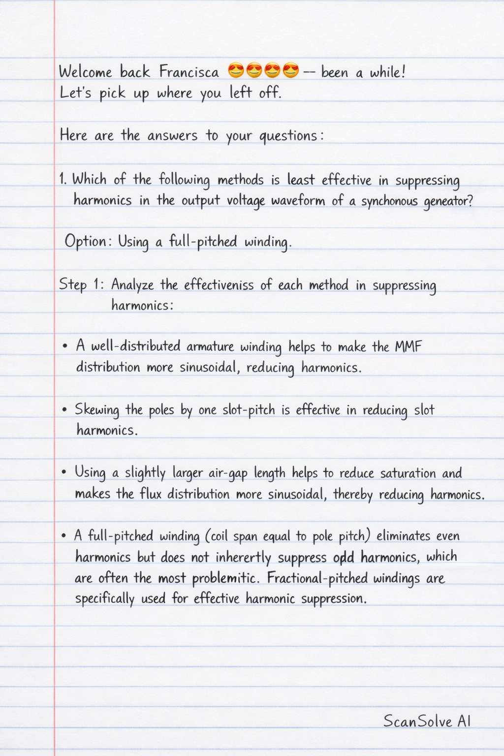
Here are the answers to your questions: 1. Which of the following methods is least effective in suppressing harmonics in the output voltage waveform of a synchronous generator? Option: Using a full-pitched winding. Step 1: Analyze the effectiveness of each method in suppressing harmonics. A well-distributed armature winding helps to make the MMF distribution more sinusoidal, reducing harmonics. Skewing the poles by one slot-pitch is effective in reducing slot harmonics. Using a slightly larger air-gap length helps to reduce saturation and makes the flux distribution more sinusoidal, thereby reducing harmonics. A full-pitched winding (coil span equal to pole pitch) eliminates even harmonics but does not inherently suppress odd harmonics, which are often the most problematic. Fractional-pitched windings are specifically used for effective harmonic suppression. Step 2: Identify the least effective method. Compared to the other methods which are actively used for harmonic reduction, a full-pitched winding is generally considered less effective for overall harmonic suppression, especially when compared to the benefits of fractional pitching. The least effective method is Using a full-pitched winding. 2. What is the primary reason that a three-phase induction motor can never run at synchronous speed? Option: If rotor speed equals synchronous speed, there would be no relative motion, thus no induced EMF, current, or torque. Step 1: Understand the principle of operation of an induction motor. An induction motor operates on the principle of electromagnetic induction. A rotating magnetic field (synchronous speed) produced by the stator induces an electromotive force (EMF) and current in the rotor conductors. The interaction between this rotor current and the stator's magnetic field produces torque, causing the rotor to rotate. Step 2: Evaluate the condition at synchronous speed. If the rotor were to run at synchronous speed, its speed would be equal to the speed of the rotating magnetic field. This would mean there is no relative motion between the rotor conductors and the magnetic field. Step 3: Determine the consequence of no relative motion. Without relative motion, no EMF would be induced in the rotor conductors. Consequently, no current would flow in the rotor, and therefore, no electromagnetic torque would be produced. Without torque, the motor cannot overcome friction and load, and thus cannot sustain synchronous speed. The primary reason is: If rotor speed equals synchronous speed, there would be no relative motion, thus no induced EMF, current, or torque. 3. If a three-phase alternator is being synchronised using the three-dark lamps method and all three lamps flicker in unison, what does this indicate? Step 1: Understand the three-dark lamps method for synchronisation. In the three-dark lamps method, lamps are connected between corresponding phases of the incoming alternator and the busbar. The goal is to connect the alternator to the busbar when the lamps are dark (indicating zero voltage difference, meaning voltages are in phase and equal) and flickering very slowly (indicating frequencies are almost matched). Step 2: Interpret "all three lamps flicker in unison". When all three lamps flicker in unison (all bright simultaneously, all dark simultaneously), it indicates that the phase sequence of the incoming alternator is correct and matches that of the busbar. If the phase sequence were incorrect, the lamps would flicker in a rotating sequence (e.g., one bright, then the next, then the third). Step 3: Interpret "flicker". The fact that the lamps are flickering at all (not steadily dark) indicates that there is still a difference in frequency between the incoming alternator and the busbar. The rate of flickering is proportional to the frequency difference. This indicates that the phase sequence of the incoming alternator is correct, but its frequency is not yet equal to the busbar frequency.