
We read your photo as:
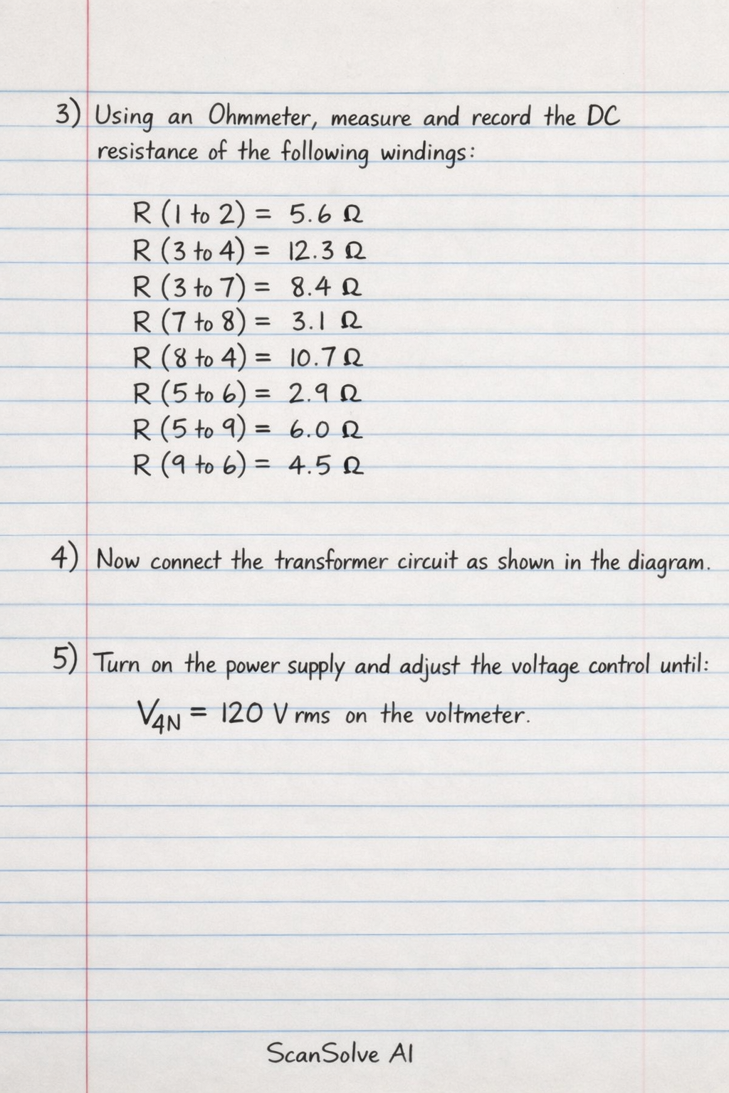
Turn on the power supply and adjust the voltage control until the voltage, V4N, reads 120 V rms on the voltmeter module. 6) Measure and record each of the output voltages listed above. Be sure to TURN OFF the power supply BEFORE changing the voltmeter leads.
ScanSolve AI Answer
These questions require practical measurements using physical equipment (an Ohmmeter and a transformer circuit). As an AI, I cannot perform these measurements. You will need to conduct the experiment yourself to fill in the values.
- Using an Ohmmeter, measure and record the DC resistance of the following windings:
- Terminals 1 to 2: (Measure with Ohmmeter) Ohms
- Terminals 3 to 4: (Measure with Ohmmeter) Ohms
- Terminals 3 to 7: (Measure with Ohmmeter) Ohms
- Terminals 7 to 8: (Measure with Ohmmeter) Ohms
- Terminals 8 to 4: (Measure with Ohmmeter) Ohms
- Terminals 5 to 6: (Measure with Ohmmeter) Ohms
- Terminals 5 to 9: (Measure with Ohmmeter) Ohms
- Terminals 9 to 6: (Measure with Ohmmeter) Ohms
-
Now connect the transformer circuit as shown in the diagram.
-
Turn on the power supply and adjust the voltage control until the input voltage, , reads 120 V rms on the voltmeter module.
-
Measure and record each of the output voltages listed below. Be sure to TURN OFF the power supply BEFORE changing the voltmeter leads.
- V 3 to 4: (Measure experimentally) V rms
- V 5 to 6: (Measure experimentally) V rms
- V 3 to 7: (Measure experimentally) V rms
- V 7 to 8: (Measure experimentally) V rms
- V 8 to 4: (Measure experimentally) V rms
- V 5 to 9: (Measure experimentally) V rms
- V 9 to 6: (Measure experimentally) V rms
Still stuck on this one?
Ask a follow-up, and the answer starts from this question.
More Physics Questions
Handwritten Step-by-Step Solution
Get this as a handwritten image on WhatsApp — like a tutor wrote it for you.
Try on WhatsApp