
We read your photo as:
Fig. 4.4 shows the elevation of a truncated cylinder at both ends. Draw full size the given view. Produce the pattern development.
ScanSolve AI Answer
Step-by-step solution
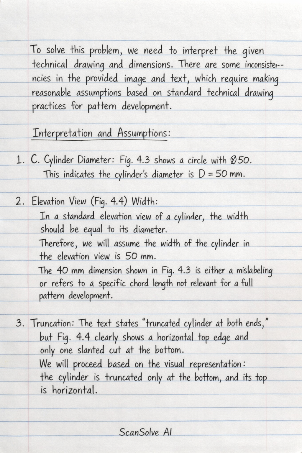
3 stepsTo solve this problem, we need to interpret the given technical drawing and dimensions. There are some inconsistencies in the provided image and text, which require making reasonable assumptions based on standard technical drawing practices for pattern development.
Interpretation and Assumptions:
- Cylinder Diameter: Fig. 4.3 shows a circle with . This indicates the cylinder's diameter is mm.
- Elevation View (Fig. 4.4) Width: In a standard elevation view of a cylinder, the width should be equal to its diameter. Therefore, we will assume the width of the cylinder in the elevation view is 50 mm, and the 40 mm dimension shown in Fig. 4.4 is either a mislabeling or refers to a specific chord length not relevant for a full pattern development.
- Truncation: The text states "truncated cylinder at both ends," but Fig. 4.4 clearly shows a horizontal top edge and only one slanted cut at the bottom. We will proceed based on the visual representation: the cylinder is truncated only at the bottom, and its top is horizontal.
- Truncation Extent: We assume the truncation extends across the full diameter of the cylinder (50 mm) in the elevation view, from one side to the other.
- Heights and Angle: The maximum height is mm, and the truncation angle is .
Part i
Draw full size the given view
To draw the full-size views, you would create the following:
-
Plan View (Fig. 4.3):
- Draw a circle with a diameter of 50 mm.
- Divide the circumference of this circle into 12 equal parts (each ) and label them (e.g., 0 to 11). These points represent the generator lines of the cylinder.
-
Elevation View (Fig. 4.4):
- Draw a rectangle with a width of 50 mm (the cylinder's diameter) and a maximum height of 80 mm.
- Project the 12 division points from the plan view onto the base of this rectangle.
- Calculate Minimum Height: The minimum height () occurs at one end of the truncation. The vertical drop across the diameter due to the angle is .
- Draw the truncated bottom edge: From the bottom-left corner of the rectangle (representing the lowest point of the truncation), draw a straight line to a point on the right vertical edge at a height of mm from the bottom. This line represents the truncation.
- Project the division points from the base of the elevation vertically upwards to the top horizontal line and to the slanted truncation line.
Part ii· 3 steps
Produce the pattern development
The pattern development (or net) of a truncated cylinder is a rectangle with a straight top edge and a curved bottom edge.
Calculate the circumference of the cylinder.
The length of the pattern development will be the circumference of the cylinder.
Determine the heights of the generator lines.
We use the 12 division points from the plan view. Let's assume point 0 is at the lowest part of the truncation (leftmost in elevation) and point 6 is at the highest part (rightmost in elevation). The horizontal distance from the lowest point of the truncation to a generator at an angle (measured from the lowest point in the plan view projection) is given by , where mm.
The height of each generator is .- mm
Let's calculate the heights for each of the 12 generator lines:
- Point 0 (): .
- Point 1 (): mm.
- Point 2 (): mm.
- Point 3 (): mm.
- Point 4 (): mm.
- Point 5 (): mm.
- Point 6 (): mm. (This is )
The heights for the remaining points are symmetrical:
Construct the pattern development.
- Draw a horizontal line representing the base of the pattern. Its length should be the circumference mm.
- Divide this line into 12 equal segments. Each segment will have a length of mm. Label these points 0, 1, 2, ..., 11, 0 (or 12).
- At each of these division points, draw a vertical line corresponding to the calculated height for that generator:
- At points 0 and 12, draw a vertical line of height 51.13 mm.
- At points 1 and 11, draw a vertical line of height 53.06 mm.
- At points 2 and 10, draw a vertical line of height 58.35 mm.
- At points 3 and 9, draw a vertical line of height 65.56 mm.
- At points 4 and 8, draw a vertical line of height 72.78 mm.
- At points 5 and 7, draw a vertical line of height 78.06 mm.
- At point 6, draw a vertical line of height 80.00 mm.
- Connect the top ends of these vertical lines with a smooth curve. This curve forms the truncated edge of the pattern.
- The top edge of the pattern development will be a straight horizontal line at a height of 80 mm, connecting the top of the and lines.
- The resulting shape is the pattern development of the truncated cylinder.
Still stuck on this one?
Ask a follow-up, and the answer starts from this question.
More Mathematics Questions
Handwritten Step-by-Step Solution
Get this as a handwritten image on WhatsApp — like a tutor wrote it for you.
Try on WhatsApp