
We read your photo as:
The elevation and plan of a cone are shown in Fig. 4.3. Draw (i) the given elevation (ii) the plan (iii) the first auxiliary elevation on plane X'-Y'.
ScanSolve AI Answer
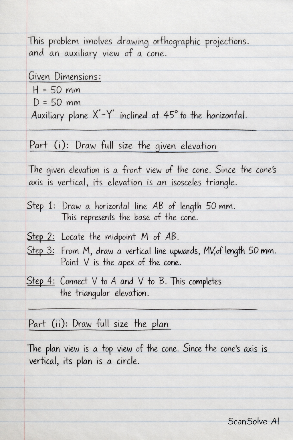
This problem involves drawing orthographic projections and an auxiliary view of a cone.
Given Dimensions:
- Cone height () = 50 mm
- Cone base diameter () = 50 mm
- Auxiliary plane X'-Y' is inclined at to the horizontal.
Part (i): Draw full size the given elevation
The given elevation is a front view of the cone. Since the cone's axis is vertical, its elevation is an isosceles triangle.
- Step 1: Draw a horizontal line of length 50 mm. This represents the base of the cone.
- Step 2: Locate the midpoint of .
- Step 3: From , draw a vertical line upwards, , of length 50 mm. Point is the apex of the cone.
- Step 4: Connect to and to . This completes the triangular elevation.
Part (ii): Draw full size the plan
The plan view is a top view of the cone. Since the cone's axis is vertical, its plan is a circle.
- Step 1: Below the elevation, draw a horizontal center line.
- Step 2: Draw a vertical center line, aligning it with the apex and the midpoint of the base in the elevation. The intersection of these center lines is the center of the cone's base in the plan view.
- Step 3: Draw a circle with a diameter of 50 mm (radius 25 mm) centered at the intersection of the center lines.
- Step 4: Divide the circumference of the circle into 12 equal parts (each ). Label these points (e.g., 0 to 11). These points represent the bases of the generator lines of the cone.
- Step 5: Project these 12 points vertically upwards to the base of the elevation. These projected points on correspond to the bases of the generator lines in the elevation.
Part (iii): Draw full size the first auxiliary elevation on plane X'-Y'
The diagram shows the X'-Y' line in the elevation view, inclined at to the horizontal. This indicates that the auxiliary plane is inclined at to the horizontal plane. For an auxiliary elevation projected from the original elevation, the view is taken perpendicular to X'-Y', and the depths are transferred from the plan view.
- Step 1: Draw the reference line X'-Y': Draw a line X'-Y' at an angle of to the horizontal. Position it conveniently, for example, passing through the lowest point of the base of the cone in the elevation (e.g., point A).
- Step 2: Project points from the elevation: Draw projection lines perpendicular to X'-Y' from the apex and from each of the 12 points on the base of the cone in the elevation.
- Step 3: Transfer depths from the plan: The distances from X'-Y' in the auxiliary view represent the depths of the points, which are measured from the center line of the plan view.
- For the apex : The apex is at the center of the plan, so its depth is 0. Therefore, the apex in the auxiliary elevation will lie on the X'-Y' line.
- For the base points (0 to 11): Measure the perpendicular distance of each point from the center line of the plan view. Let be the radius (25 mm).
- Points on the center line (e.g., 0 and 6): Depth = 0. These points will lie on the X'-Y' line.
- Points at from center line (e.g., 1 and 11, 5 and 7): Depth = mm.
- Points at from center line (e.g., 2 and 10, 4 and 8): Depth = mm.
- Points at from center line (e.g., 3 and 9): Depth = mm.
- Plot these depths along the corresponding projection lines from X'-Y'. For example, for point 3, measure 25 mm perpendicular to X'-Y' along its projection line.
- Step 4: Complete the auxiliary elevation:
- Connect the plotted points for the base with a smooth curve to form an ellipse. This is the elliptical base of the cone in the auxiliary view.
- Connect the apex (which lies on X'-Y') to the extreme points of the elliptical base to complete the auxiliary elevation of the cone.
The final drawing will show:
- An isosceles triangle for the elevation.
- A circle for the plan, divided into 12 segments.
- An auxiliary view showing the cone as if tilted, with an elliptical base and the apex on the X'-Y' line, projected perpendicular to the inclined X'-Y' line.
Still stuck on this one?
Ask a follow-up, and the answer starts from this question.
More Mathematics Questions
Handwritten Step-by-Step Solution
Get this as a handwritten image on WhatsApp — like a tutor wrote it for you.
Try on WhatsApp