
We read your photo as:
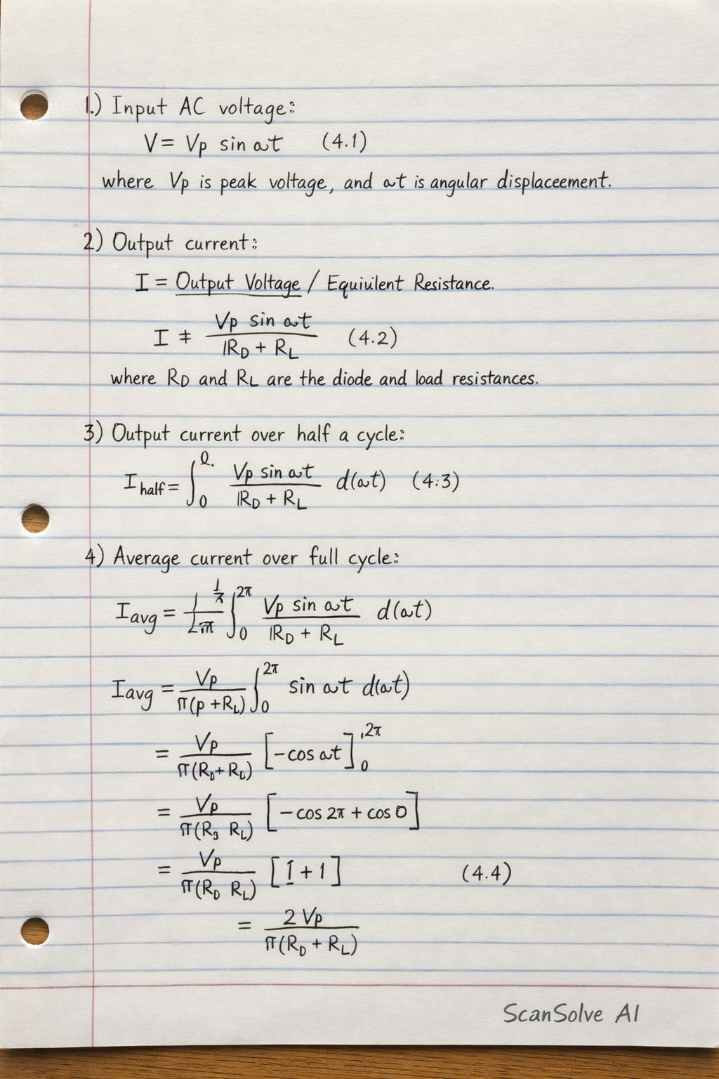
Input AC voltage
ScanSolve AI Answer
Here is the information extracted from the image:
Input AC voltage
If the voltage across the secondary coil of the transformer is:
where is peak voltage and is angular displacement of the rotating coil in the alternator or input signal generator.
Output current
Output current is given by:
where and are resistances of diode and load respectively.
Output current taken over half a cycle
Output current taken over half a cycle as illustrated in Figure 4.5a is given as:
Average current taken over a full cycle
Average current taken over a full cycle and illustrated in Fig. 4.5b is given as:
(The formula for this section is cut off in the image and cannot be fully transcribed.)
Still stuck on this one?
Ask a follow-up, and the answer starts from this question.
More Physics Questions
Handwritten Step-by-Step Solution
Get this as a handwritten image on WhatsApp — like a tutor wrote it for you.
Try on WhatsApp